Engraving and milling machine

A technology of engraving and milling machine and frame, which is applied in the direction of metal processing machinery parts, clamping, supporting, etc. It can solve the problems of high precision and processing of difficult-shaped workpieces, and achieve high processing accuracy, convenient and stable clamping, and lifting clamping The effect of precision

Pending Publication Date: 2019-11-22
吴善旺
View PDF1 Cites 7 Cited by
  • Summary
  • Abstract
  • Description
  • Claims
  • Application Information

AI Technical Summary

Problems solved by technology

[0004] The purpose of the present invention is to solve the above-mentioned problems in the existing technology, and propose an engraving and milling machine. The present invention solves the problem that the existing engraving and milling machine is difficult to process high-precision workpieces with special shapes

Method used


Image

  • Engraving and milling machine
  • Engraving and milling machine
  • Engraving and milling machine

Examples


Embodiment 1

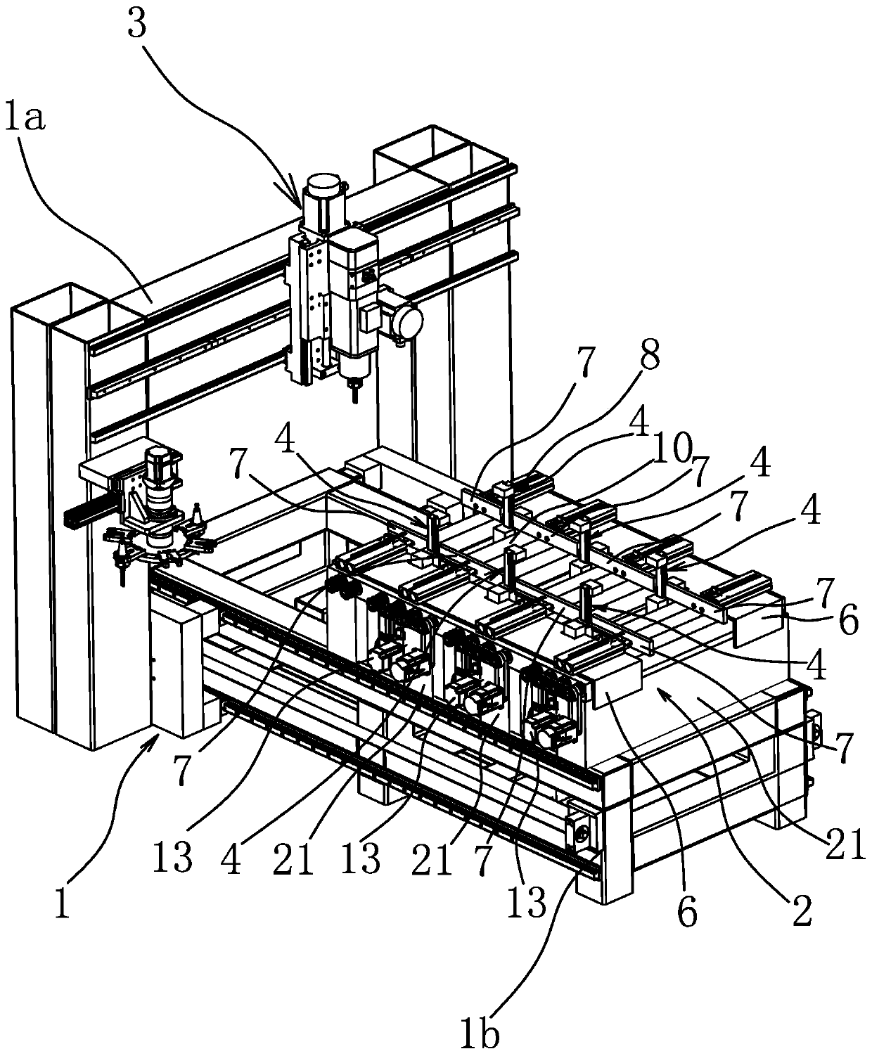
[0040] like figure 1 As shown, the engraving and milling machine includes a frame 1, the frame 1 includes a base 1b, the base 1b is provided with a work platform 2 for placing workpieces, and the base 1b is also provided with a gantry 1a that can slide longitudinally. The engraving assembly 3 is provided on the frame 1a, and the engraving assembly 3 can also move laterally and up and down relative to the gantry 1a, so that the engraving assembly 3 can perform three-dimensional translation relative to the working platform 2. Of course, as another situation, the position of the gantry 1a relative to the base 1b may also be fixed, and the working platform 2 can move longitudinally on the base 1b.

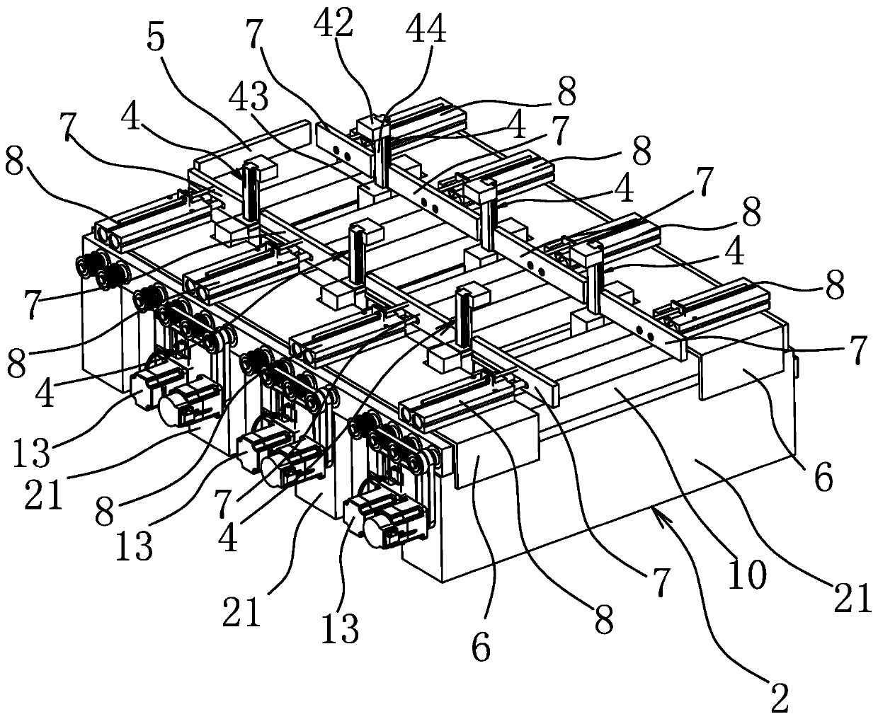
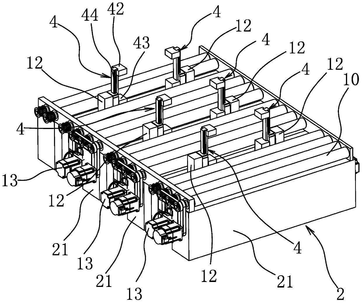
[0041] like figure 2 As shown, two rows of clamping parts 4 that can clamp the workpiece from the side of the workpiece are arranged at intervals along the transverse direction on the working platform 2, and the number of clamping parts 4 in each row is three and arranged at interval...

Embodiment 2

[0051] The structure and principle of this embodiment are basically the same as that of Embodiment 1, the difference lies in: the quantity and arrangement of clamping parts 4 are different, such as Figure 15 As shown, the number of clamping parts 4 on the working platform 2 is three, and the three clamping parts 4 are arranged at intervals along the longitudinal direction of the working platform. Each clamping part 4 can move horizontally and horizontally relative to the working platform 2 independently move. This structure is mainly used for processing special-shaped workpieces with small width. During processing, the workpiece relies on the side backing 7 and the front backing 5 on the working platform 2, so that the workpiece is positioned at a preset position, and then depends on the movement of the three clamping parts 4 to clamp the workpiece first. During the processing, by retracting one clamping part 4 away from the workpiece each time, and relying on the other two ...

Embodiment 3

[0053] The structure and principle of this embodiment are basically the same as that of the first embodiment, except that four clamping parts 4 are arranged on the engraving platform, and the four clamping parts 4 are arranged in two rows along the horizontal direction of the working platform 2 .


PUM


Abstract

The invention provides an engraving and milling machine, belongs to the technical field of engraving equipment, and solves the problem that it is hard for engraving and milling machines to perform high-precision machining on specially-shaped workpieces in the prior art. The engraving and milling machine comprises a rack and a working platform which is arranged on the rack and used for placing a workpiece; an engraving component which can perform three-dimensional translation relative to the working platform is further arranged on the rack; three or more clamping pieces are arranged on the working platform; any clamping piece is located on one side of the workpiece and can move independently relative to the working platform; and any clamping piece can move in the direction far away from theworkpiece, so that the engraving component can machine contact part, acted by the clamping piece, of the workpiece. The engraving and milling machine has the advantage of high machining precision forthe specially-shaped workpiece.

Description

technical field [0001] The invention belongs to the technical field of engraving equipment, and relates to an engraving and milling machine. Background technique [0002] Engraving and milling machine is a combination of drilling and milling equipment. Compared with manual engraving, it has higher processing efficiency and processing accuracy, so it has been widely used, and has even replaced manual engraving technology. The emergence of engraving and milling machine It has laid the foundation for mass and rapid production of products. [0003] In the process of machining the workpiece, the engraving and milling machine involves the clamping and positioning of the workpiece, and the level and stability of the clamping accuracy directly affect the processing accuracy. At present, for the clamping of the workpiece, it is conventional to clamp the workpiece from both ends of the workpiece through the top and the turntable, such as an adjustable eight-head five-axis three-dimen...

Claims


Application Information

Patent Timeline
Patent Type & Authority Applications(China)
IPC IPC(8): B23Q3/06B23Q3/08B23P23/02
CPCB23P23/02B23Q3/06B23Q3/08B23Q3/082B23Q2703/04
Inventor 吴善旺
Owner 吴善旺
Why Eureka
Try Eureka