Overturning mechanism of engraving and milling machine

A technology of turning mechanism and engraving and milling machine, which is applied in the direction of multi-purpose machinery, forming/shaping machine, special forming/shaping machine, etc., and can solve problems such as difficult to realize efficient automatic processing

Pending Publication Date: 2019-12-20
吴善旺
View PDF12 Cites 0 Cited by
  • Summary
  • Abstract
  • Description
  • Claims
  • Application Information

AI Technical Summary

Problems solved by technology

[0005] The purpose of the present invention is to solve the above-mentioned problems in the existing technology, and propose a turning mechanism of an engraving and milling machine to solve the problem that the existing engraving and milling machine is difficult to realize efficient automatic processing for different sides of wood

Method used


Image

  • Overturning mechanism of engraving and milling machine
  • Overturning mechanism of engraving and milling machine
  • Overturning mechanism of engraving and milling machine

Examples


Embodiment 1

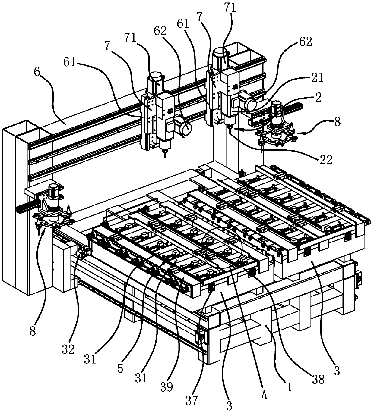
[0033] Such as figure 1 , figure 2 As shown, the turning mechanism of the engraving and milling machine, the engraving and milling machine includes a frame 1, a processing assembly 2 and a processing platform 3, and a gantry 6 is arranged to slide longitudinally on the frame 1, and the gantry 6 is carried out through the cooperation of the longitudinal motor and the screw nut assembly. Longitudinal drive, tool magazines 8 are provided on the columns on both sides, and two horizontal carriages 61 are slidingly connected to the upper part of the gantry 6 along the transverse direction, and each horizontal carriage 61 is connected with a rack and pinion assembly Cooperate to carry out horizontal drive, on each horizontal carriage 61, all slide vertically and be connected with vertical carriage 7, on each vertical carriage 7, all vertically drive by vertical motor 71 and screw nut assembly, each A processing assembly 2 is provided on the vertical carriage 7, and the processing a...

Embodiment 2

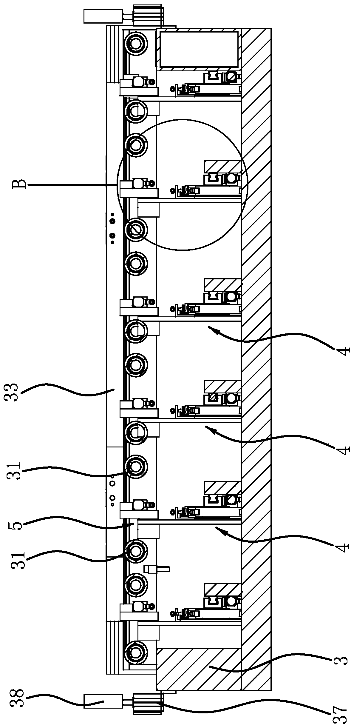
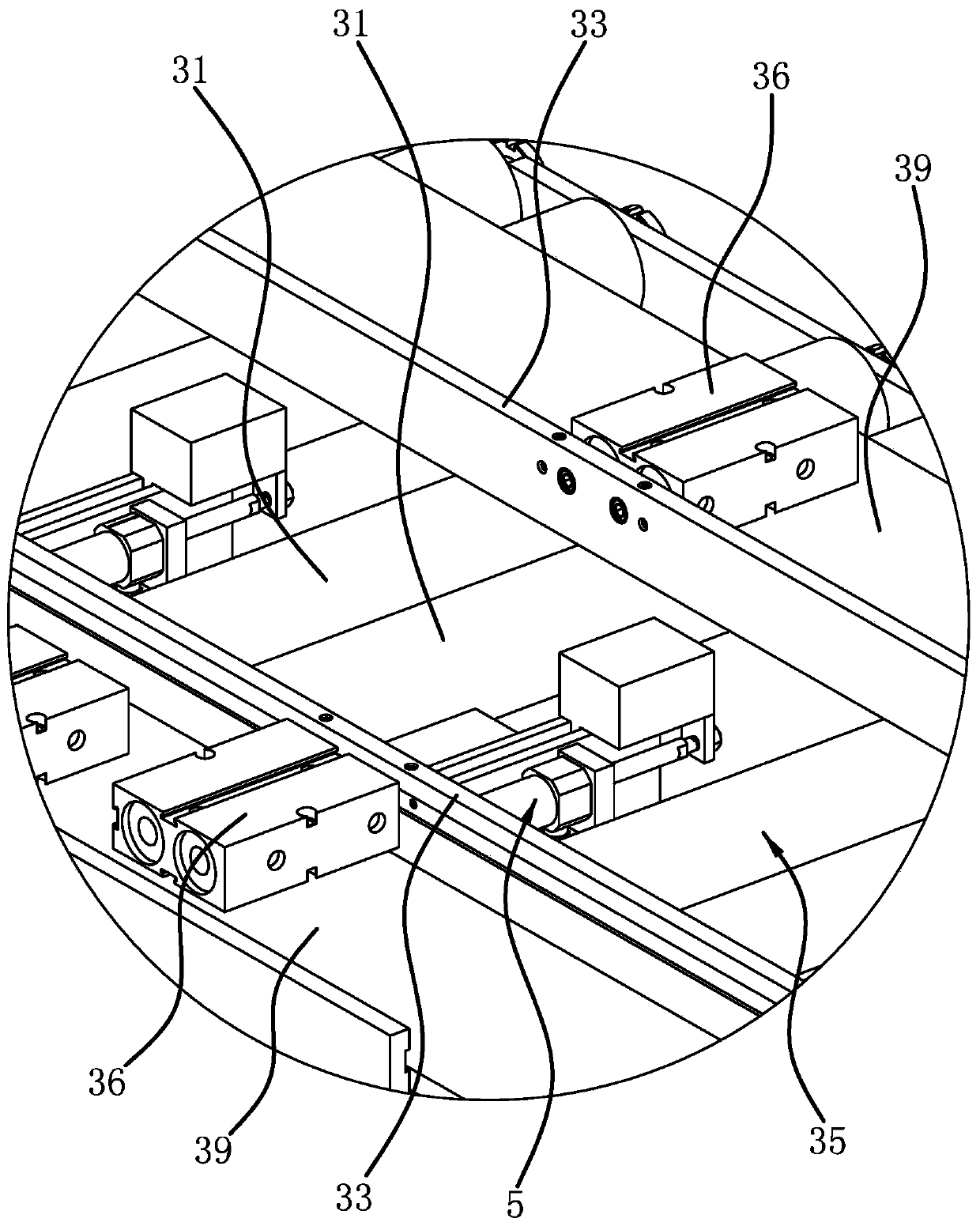
[0038] The turning mechanism of the engraving and milling machine is basically the same as the structure of the first embodiment, the difference is as follows: Figure 7 As shown, each feed channel 35 is correspondingly provided with a set of positioning components, each positioning component includes a strip-shaped splint 34 arranged longitudinally and several lateral backers, and several guide rails are fixed on the processing platform 3. The guide rails are arranged vertically, and each guide rail is arranged horizontally. A horizontal backer 33 is also fixed on the guide rail. The horizontal backer 33 is block-shaped, and several horizontal backers 33 are arranged vertically, and are fixed between adjacent two horizontal backers 33 Longitudinal guide rods 30 are arranged, and these several longitudinal guide rods 30 are arranged in rows along the longitudinal direction, and the longitudinal guide rods 30, the transverse backers 33 and the clamping plates 34 are all position...

Embodiment 3

[0040] The turning mechanism of the engraving and milling machine is basically the same as the structure of the first embodiment, the difference is that the gantry 6 is fixed on the frame 1, and correspondingly, the processing platform 3 is slid and connected to the frame 1 in the longitudinal direction, and The motor cooperates with the screw nut assembly to drive the processing platform 3 to move longitudinally.


PUM


Abstract

The invention provides an overturning mechanism of an engraving and milling machine, and belongs to the technical field of machining equipment. The problem that an existing engraving and milling machine is difficult to realize high-efficiency automatic machining aiming at different side surfaces of wood is solved. According to the overturning mechanism of engraving and milling machine, the engraving and milling machine comprises a rack and a machining assembly and a machining platform, wherein the machining assembly and the machining platform are arranged on the rack, the machining assembly can achieve three-dimensional translation relative to the machining platform, a plurality of feeding rollers arranged in parallel are arranged on the machining platform in the longitudinal direction, the overturning mechanism comprises a clamp capable of clamping the wood and driving the wood to overturn, the machining platform is provided with a moving assembly, the clamp is arranged on the movingassembly, the moving assembly can drive the clamp to move in the vertical direction, the clamp is located between two adjacent feeding rollers, and when the clamp moves upwards, the clamp can be higher than the feeding roller. The overturning mechanism of the engraving and milling machine realizes automatic machining on different sides of the wood.

Description

technical field [0001] The invention belongs to the technical field of mechanical processing equipment, and relates to a turning mechanism of an engraving and milling machine. Background technique [0002] Engraving and milling machine is a kind of CNC machine tool, which can be used for both engraving and milling. It is a high-efficiency and high-precision CNC machine tool with a wide range of applications. For example, the engraving and milling machine disclosed in the patent document (201510945613.7) includes machine base, Horizontal moving table, support plate, moving device and engraving and milling mechanism, horizontal moving table is connected to machine base through driving mechanism, positioning supporting mechanism is arranged on the top surface of horizontal moving table, moving device includes positioning frame and moving mechanism, positioning frame A first motor is arranged on one side, and a limit block is arranged on the other side of the positioning frame. ...

Claims


Application Information

Patent Timeline
Patent Type & Authority Applications(China)
IPC IPC(8): B27C5/02B27C5/06B27C9/04
CPCB27C5/02B27C5/06B27C9/04
Inventor 吴善旺
Owner 吴善旺
Why Eureka
Try Eureka