Charging gun assembly and charging method

A charging gun and assembly technology, applied in charging stations, electric vehicle charging technology, circuits, etc., can solve problems such as the loss of the charging gun assembly, and achieve the effect of ensuring safety and stability, reducing wear and tear, and ensuring personal safety.

Pending Publication Date: 2019-11-22
浙江致威电子科技有限公司
View PDF0 Cites 7 Cited by
  • Summary
  • Abstract
  • Description
  • Claims
  • Application Information

AI Technical Summary

Problems solved by technology

[0004] In view of this, the embodiment of the present invention provides a charging gun assembly and a charging method to...

Method used


Image

  • Charging gun assembly and charging method
  • Charging gun assembly and charging method
  • Charging gun assembly and charging method

Examples


specific Embodiment approach

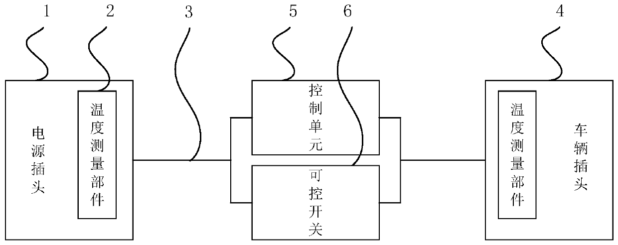
[0047] Specific implementation methods, such as figure 2 shown, including:

[0048] A control unit 5, arranged between the power plug 1 and the vehicle plug 4, and connected through the charging cable 3;

[0049] A controllable switch 6 is arranged on the charging cable 3;

[0050] Wherein, the temperature measuring component 2 is connected with the control unit 5, and a controllable switch 6 is arranged in the control unit 5.

[0051] Optionally, the controllable switch 6 may be connected to the control unit 5, and after the control unit 5 sends a charging signal, the controllable switch 6 is closed to start charging.

[0052] Specifically, the control unit 5 also includes a power supply control device connected to the vehicle control device.

[0053] Specifically, an equivalent resistance and an equivalent diode are connected between the power supply control device and the vehicle control device, wherein one end of the equivalent resistance is connected to the pulse widt...

Embodiment approach

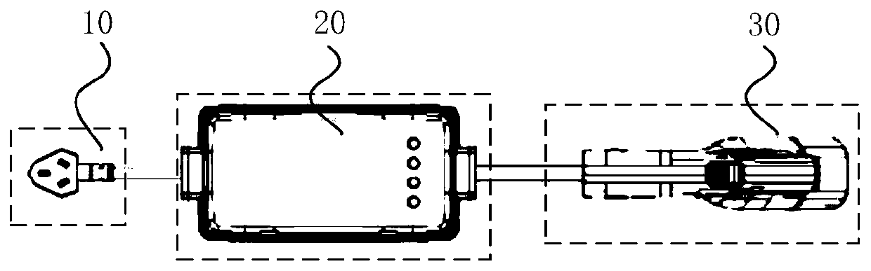
[0073] like image 3 As shown in -4, the charging gun assembly with three plugs and thermal protection is a charging connection device, which adopts charging mode two connection method B.

[0074] Its basic structure includes: three plugs 10 with thermal protection, an on-cable control box 20 , a charging cable 3 , and a vehicle plug 4 .

[0075] Specifically, the control charging method of the three-plug charging gun assembly with thermal protection includes:

[0076] The first step is to ensure the connection: insert the vehicle plug 4 into the vehicle socket, and insert the three plugs into the household AC socket;

[0077] The second step is to start charging: the power supply control device of the cable control box 20 maintains signal communication with the vehicle control device of the electric vehicle, and the electric vehicle notifies the cable control box 20 to start charging. The control box 20 on the cable controls the controllable switch 6, pulls K1 and K2 into c...


PUM


Abstract

The invention relates to the technical field of automobile electronics, in particular to a charging gun assembly and a charging method. The charging gun assembly comprises: a power plug, a vehicle plug and a charging cable used for connecting the power plug and the vehicle plug; a temperature measuring part arranged in the power plug and/or the vehicle plug; a control unit arranged between the power plug and the vehicle plug and connected with the power plug and the vehicle plug through the charging cable; the temperature measuring part is connected with the control unit, and a controllable switch is arranged in the control unit. The power plug is detected by the temperature measuring part, and/or the temperature of the vehicle plug changes, so the current change can be safely and reliablydetected; temperature rise caused by large current generated by current fluctuation of a mains supply network is found in time, the control unit is used for monitoring temperature and stabilizing current output, so safety and stability of vehicle body charging are guaranteed, loss of the charging gun assembly due to forced outage is reduced, and the safety problem of the vehicle body and a humanbody is avoided.

Description

technical field [0001] The invention relates to the technical field of automotive electronics, in particular to a charging gun assembly and a charging method. Background technique [0002] With the rapid development of the new energy vehicle industry, many car owners choose to buy new energy vehicles. The main driving method of new energy vehicles is to convert electric energy into kinetic energy. However, in order to supply power (provide kinetic energy) to new energy vehicles, it is necessary to have a suitable charging gun assembly as a charging medium to charge the electric energy required by new energy vehicles. The medium is passed to the new energy vehicle for charging. [0003] In the existing charging gun assembly, the working principle of converting alternating current into high-voltage direct current suitable for the vehicle voltage platform is mainly used. In the existing charging gun assembly, in order to facilitate charging, ordinary three-plugs are usually u...

Claims


Application Information

Patent Timeline
IPC IPC(8): B60L53/16H01R31/06H01R13/66H01R13/70
CPCB60L53/16H01R13/665H01R13/6683H01R13/70H01R31/065H01R2201/26Y02T10/70Y02T10/7072Y02T90/14
Inventor 林仕法赵顺荣黄李洁
Owner 浙江致威电子科技有限公司
Why Eureka
Try Eureka