Charging coil and wireless charging terminal

A charging coil and coil technology, applied in the direction of transformer/inductor coil/winding/connection, circuit, inductor, etc., can solve problems such as increasing the resistance of charging coil, reduce distributed capacitance, improve efficiency, and increase cross-sectional area Effect

Active Publication Date: 2020-07-03
AKM ELECTRONICS INDAL PANYU
View PDF6 Cites 0 Cited by
  • Summary
  • Abstract
  • Description
  • Claims
  • Application Information

AI Technical Summary

Problems solved by technology

Solve the problem in the prior art that increasing the natural vibration frequency of the charging coil will increase the resistance of the charging coil at the same time

Method used


Image

  • Charging coil and wireless charging terminal
  • Charging coil and wireless charging terminal
  • Charging coil and wireless charging terminal

Examples


Embodiment Construction

[0034] In order to make the technical problems solved by the embodiments of the present invention, the technical solutions adopted and the technical effects achieved clearer, the technical solutions of the present invention will be further described below in conjunction with the accompanying drawings and through specific implementation methods. It should be understood that the specific embodiments described here are only used to explain the present invention, but not to limit the present invention. In addition, it should be noted that, for the convenience of description, only parts related to the present invention are shown in the drawings but not all content. Before discussing the exemplary embodiments in more detail, it should be mentioned that some exemplary embodiments are described as processes or methods depicted as flowcharts.

[0035] A charging coil and a wireless charging terminal provided by the embodiments of the present invention are suitable for wireless charging...


PUM

PropertyMeasurementUnit
heightaaaaaaaaaa
thicknessaaaaaaaaaa
thicknessaaaaaaaaaa

Abstract

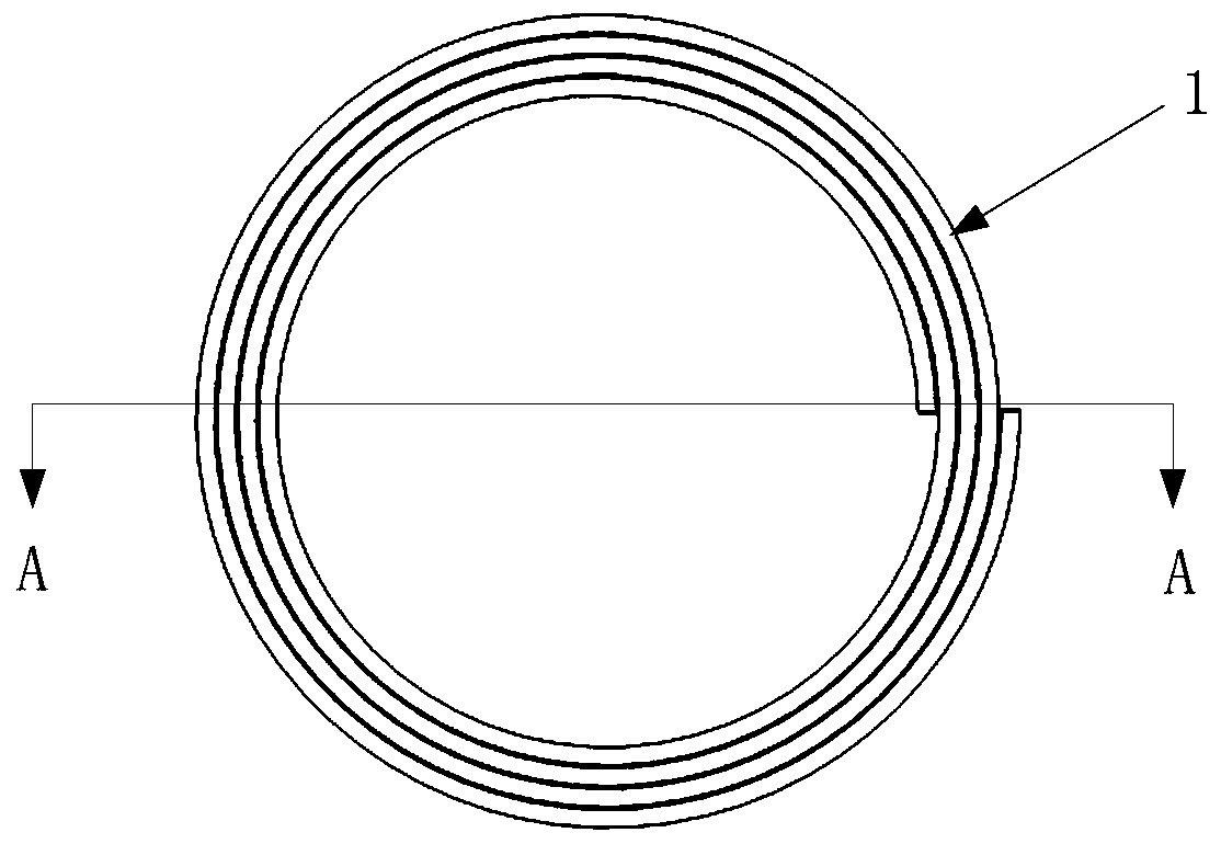
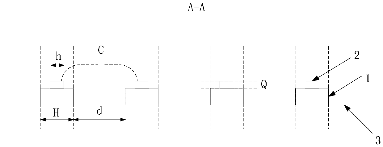
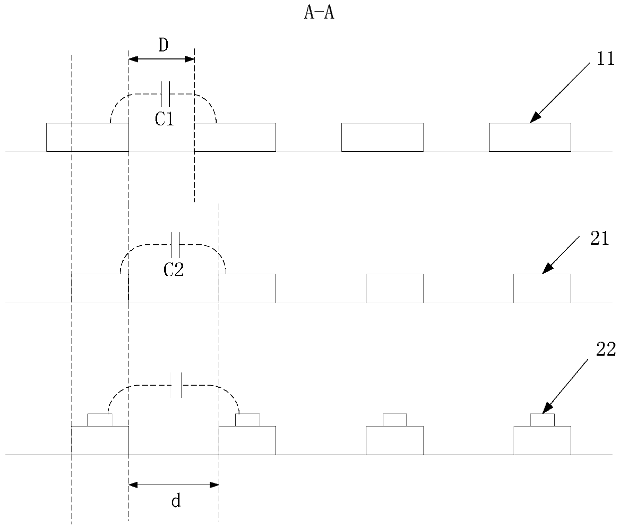
Embodiments of the invention disclose a charging coil and a wireless charging terminal. The charging coil comprises a flexible substrate, a coil body and a coil clad layer which are arranged in a laminated manner, wherein the flexible substrate is used for providing support for the charging coil; the coil body comprises a plurality of turns of coils, and a distance between every two adjacent turnsof coils is 110-180 [mu]m; and the coil clad layer is arranged on the surface of one side, far away from the flexible substrate, of at least part of the coil body. According to the charging coil provided by the embodiments of the invention, the resistance of the coil can be reduced and coil heating and energy loss are prevented on the premise of improving the self-resonant frequency of the coil.

Description

technical field [0001] The embodiments of the present invention relate to the technical field of wireless charging, and in particular to a charging coil and a wireless charging terminal. Background technique [0002] The current wireless charging coils of electronic products are all based on flexible circuit boards. Among them, inductance, DC resistance, AC resistance and self-resonant frequency have a great influence on the electrical performance of coils made of flexible circuit boards. Inductance will affect Coupling degree of the coil, the resistance will cause the coil to heat up, and the distributed capacitance and inductance of the coil will jointly affect the self-resonant frequency of the coil. [0003] In actual production, due to the limitation of processing technology, the natural vibration frequency of the coil will be high or low. because Among them, L is the inductance of the coil, and C is the distributed capacitance of the coil. Therefore, when the self-...

Claims


Application Information

Patent Timeline
Patent Type & Authority Applications(China)
IPC IPC(8): H01F27/30H01F27/28H01F38/14H02J50/12
CPCH01F27/306H01F27/28H01F38/14H02J50/12
Inventor 齐伟郑玉川董异文宋国光刘友军彭先庆
Owner AKM ELECTRONICS INDAL PANYU
Why Eureka
Try Eureka