
Electron multiplying charge coupled device (EMCCD) drive circuit based on autotransformer

A technology of autotransformer and drive circuit, which is applied in TV, electrical components, color TV, etc., can solve the problems of small output power, self-excited oscillation output current, influence of distributed parameter circuit, etc., and achieve lower requirements, low power consumption, Effect of Power Consumption Reduction

Active Publication Date: 2013-05-15
长春长光精密仪器集团有限公司
View PDF5 Cites 4 Cited by
  • Summary
  • Abstract
  • Description
  • Claims
  • Application Information

AI Technical Summary

Problems solved by technology

[0004] The present invention solves the problem that in the existing driving circuit, due to the increase of the operating frequency, the AC and DC losses of the ordinary transformer increase and the distribution parameters have a serious impact on the circuit. The operation amplifier is limited by the operating frequency and output voltage range, and is prone to self-excitation. Oscillation and the problem of low output current and low output power provide an EMCCD drive circuit based on an autotransformer

Method used


Image

  • Electron multiplying charge coupled device (EMCCD) drive circuit based on autotransformer
  • Electron multiplying charge coupled device (EMCCD) drive circuit based on autotransformer
  • Electron multiplying charge coupled device (EMCCD) drive circuit based on autotransformer

Examples


specific Embodiment approach 1

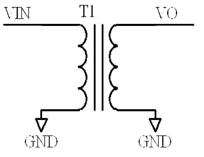
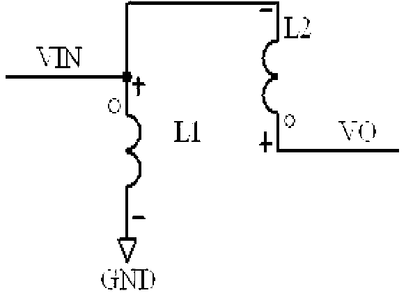
[0015] Specific implementation mode 1. Combination Figure 1 to Figure 4 Describe this embodiment, an EMCCD drive circuit based on an autotransformer, the circuit includes a timing generator, an integrated drive circuit, an autotransformer, a DC blocking coupling circuit, a controller, an adjustable low-voltage power supply, a DC blocking circuit, and a filter circuit and clamping circuit; the controller is connected to the timing generator and the adjustable low-voltage power supply, and through real-time control of the timing generator, the timing generator outputs a high-speed timing signal with a fixed level and a finely adjustable phase, which is sent to the integrated driver; adjustable The low-voltage power supply is connected to the integrated driver to supply power for the integrated driver; the adjustable low-voltage power supply is controlled by the controller, and the amplitude of the output signal of the integrated driver can be changed by changing the output volta...


PUM


Abstract

The invention provides an electron multiplying charge coupled device (EMCCD) drive circuit based on an autotransformer, relates to a drive method of a charge coupled device (CCD) and in particular to an EMCCD high speed high voltage drive signal achieving method with frequency reaching 35MHz. The EMCCD drive circuit based on the autotransformer mainly solves the problem that an existing drive method is difficult to realize. A high speed high voltage drive signal is obtained through an autotransformer resonance circuit; a clamping circuit composed of a plurality of clamping diodes in series connection guarantees that a low level value of a high speed high voltage output signal satisfies an application requirement; digital control can be conducted on the amplitude of the output signal so that a highest level value of the output signal is controlled; and distributed capacitance and consumption of the circuit are reduced through reducing the number of turns of coils, power required to be input is low under the condition of the same output signal and the EMCCD drive circuit based on the autotransformer can be used in the application of high frequency.

Description

technical field [0001] The invention relates to a CCD driving technology, in particular to a method for realizing an EMCCD high-speed and high-voltage driving signal whose frequency can reach 35 MHz. Background technique [0002] When imaging a darker target, if the noise of the CCD's readout amplifier is relatively large, it will often cover up the useful signal, especially when the readout speed is high, and the readout noise will increase with the increase of the readout speed . With the continuous development of CCD manufacturing technology, the advent of EMCCD enables tiny signals to overcome the noise of the readout amplifier, and this type of CCD can obtain image quality similar to that of ICCD without any additional structure; TI company The basic structure of the EMCCD is roughly the same as the traditional frame transfer CCD, but hundreds of gain registers are added between the readout register and the sense amplifier, and its electrode structure is different from...

Claims


Application Information

Patent Timeline
Patent Type & Authority Applications(China)
IPC IPC(8): H04N5/372H04N5/357
Inventor 余达刘金国郭永飞司国良薛旭成李云飞李洪法
Owner 长春长光精密仪器集团有限公司
Learn More