Coiling method for annular inductor and annular inductor

A technology of toroidal inductance and winding method, applied in transformer/inductor parts, transformer/inductor coil/winding/connection, inductance with magnetic core, etc., can solve the difficult application of differential mode inductance and PFC inductance, etc. question

Active Publication Date: 2017-02-22
GUANGZHOU DECI ELECTRONICS DEVICE
View PDF9 Cites 4 Cited by
  • Summary
  • Abstract
  • Description
  • Claims
  • Application Information

AI Technical Summary

Problems solved by technology

Although this winding method can meet the electromagnetic interference requirements of toroidal common mode inductors, it is difficult to apply to diff

Method used


Image

  • Coiling method for annular inductor and annular inductor

Examples


Embodiment 1

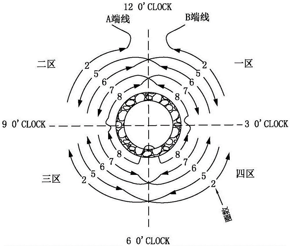
[0030] see figure 1 , the winding method of the toroidal inductor of this embodiment is to divide the toroidal core into four winding areas on average, divide the copper wire into two halves, one end of the copper wire is wound clockwise along the toroidal magnetic core, and the other end of the copper wire The wire is wound along the ring-shaped magnetic core in the counterclockwise direction, and the copper wire is flat and densely wound in the four winding areas to form four copper coil groups, and there are gaps between the copper coil groups in the adjacent winding areas.

[0031] Among them, the half of the copper wire around the ring core is taken as the 6 o'clock direction, one end of the copper wire is used as the A-end wire, and the other end of the copper wire is used as the B-end wire, and the A-end wire of the copper wire passes through the 9 o'clock direction from the 6 o'clock direction. The clock direction is then wound to the direction of 12 o'clock, and the B...

Embodiment 2

[0039] The main technical solution of this embodiment is basically the same as that of Embodiment 1, and the features not explained in this embodiment are explained in Embodiment 1, and will not be repeated here. The difference between this embodiment and Embodiment 1 is that the copper wire is wound in 4 layers on the toroidal magnetic core, and when the first layer of copper wire is wound, each winding area is wound 9 times; the second layer of copper wire is wound When the copper wire is wound on the third layer, each winding area is wound 7 times; when the copper wire is wound on the fourth layer, each winding area is wound 4 times.

Embodiment 3

[0041] The main technical solution of this embodiment is basically the same as that of Embodiment 1, and the features not explained in this embodiment are explained in Embodiment 1, and will not be repeated here. The difference between this embodiment and Embodiment 1 is that the copper wire is wound in one layer on the toroidal magnetic core, and when the copper wire is wound in the first layer, each winding area is wound 10 times.

[0042] Example 3

[0043] The winding of the anti-electromagnetic interference differential mode inductor in this embodiment is wound using the winding method of the ring inductor in Embodiment 1.


PUM


Abstract

The invention discloses a coiling method for an annular inductor. The coiling method includes the steps that an annular magnetic core is evenly divided into four coiling regions, a copper wire is symmetrically folded, one end of the copper wire is clockwise coiled around the annular magnetic core, and the other end of the copper wire is anticlockwise coiled around the annular magnetic core; the copper wire is flatly and densely coiled in the four coiling regions to form four copper coil sets, and gaps are reserved between the copper coil sets of the adjacent coiling regions. Compared with the prior art, the copper wire is symmetrically folded, the two ends are coiled around the annular magnetic core, the four coiling regions are formed on the annular magnetic core, the copper wire is flatly and densely coiled around the coiling regions, the gaps are reserved between the adjacent coiling regions for obviously partitioning, and the method is called 'a quadrant coiling method'; the coiling method can be suitable for copper wire coiling of the difference module inductor and the PFC inductor, the defects that existing coiling methods are low in efficiency and poor in electromagnetic interference resistance are overcome, the resistance of the inductor is obviously increased, the distributed capacitance of the inductor is small, and coiling working efficiency is high.

Description

technical field [0001] The invention relates to the technical experience of an inductor winding method, in particular to a ring-shaped inductor winding method and a differential mode inductor and a PFC inductor using the winding method. Background technique [0002] An inductor (Inductor) is a component that can convert electrical energy into magnetic energy and store it. It is generally composed of a skeleton, windings, shields, packaging materials, magnetic cores or iron cores. Winding refers to a group of coils with specified functions, which is the basic component of inductors. The winding can be divided into single-layer and multi-layer, and the single-layer winding has two forms: dense winding (the wires are next to each other when winding) and inter-winding (there is a certain distance between each wire when winding); There are many kinds of multilayer windings, such as layered flat winding, random winding, and honeycomb winding. The winding method has a great influ...

Claims


Application Information

Patent Timeline
IPC IPC(8): H01F41/066H01F41/08H01F17/06H01F27/30
CPCH01F17/06H01F27/306H01F41/08
Inventor 汪建枝汪民
Owner GUANGZHOU DECI ELECTRONICS DEVICE
Why Eureka
Try Eureka