Steel wire rope winding device

A winding device and steel wire rope technology, applied in the field of steel wire rope, can solve the problems of consumption, heavy physical strength, looseness, etc., and achieve the effect of avoiding the loosening of the wire rope

Inactive Publication Date: 2019-11-22
NANJING LISHUI HIGH-TECH VENTURE CAPITAL MANAGEMENT CO LTD
View PDF10 Cites 5 Cited by
  • Summary
  • Abstract
  • Description
  • Claims
  • Application Information

AI Technical Summary

Problems solved by technology

[0002] After the steel wire rope is processed, it is necessary to wind the steel wire rope on the reel, but when winding the steel wire rope on the reel, it is necessary to fix or clamp one end of the steel wire rope to the reel first, so that the steel wire rope can be wound On the reel, generally in the process of fixing or clamping one end of the wire rope, workers need to use tools to turn the bolts to fix or clamp the wire rope. In the process of turning the bolts, the workers need to consume huge physical strength, and it is very It is difficult to ensure that one end of the wire rope is clamped completely, which may make the clamped end of the wire rope loose

Method used


Image

  • Steel wire rope winding device
  • Steel wire rope winding device
  • Steel wire rope winding device

Examples


Embodiment Construction

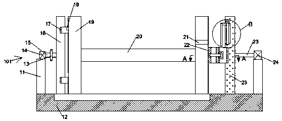
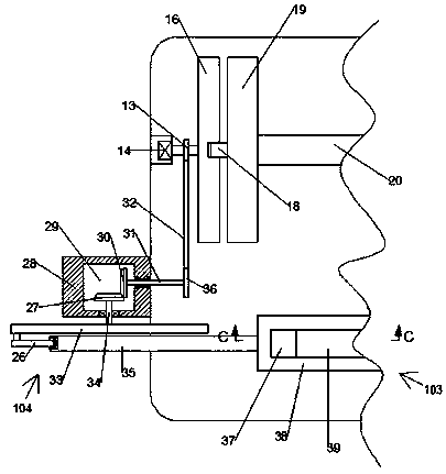
[0019] Combine below Figure 1-5 The present invention is described in detail, and for convenience of description, the orientations mentioned below are now stipulated as follows: figure 1 The up, down, left, right, front and back directions of the projection relationship itself are the same.

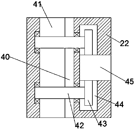
[0020] refer to Figure 1-5 , a wire rope winding device according to an embodiment of the present invention, comprising a fixed table 12, on which a rotating disc 19 is symmetrically arranged left and right, and a rotating rod 20 is fixedly installed between the rotating discs 19 on the left and right sides The left side of the rotating disk 19 on the left side is provided with a power mechanism 101 that can drive the rotating disk 19 to rotate, and the right side of the rotating disk 19 on the right side is fixedly installed with a fixed box 22, and the fixed box 22 is equipped with There is a clamping cavity 41, the clamping plate 40 is slidably installed in the clamping cavity 41, ...


PUM


Abstract

The invention discloses a steel wire rope winding device. The steel wire rope winding device comprises a fixing table, wherein rotating discs are symmetrically arranged on the left side and the rightside of the fixing table, and a rotating rod is fixedly arranged between the rotating discs on the left side and the right side. A transmission rod rotates to drive a first bevel gear to rotate; the first bevel gear is engaged with a second bevel gear to drive a gear rod to rotate; a steel wire rope passes between clamping rods on the front side and the rear side after penetrating through a through hole, and a second motor drives a rack to move downward, so that the rack drives a first gear to rotate; the first gear rotates to enable a clamping plate to move leftwards to clamp the steel wire rope, so that the steel wire rope can be well clamped by the clamping plate, and the situation that the steel wire rope loosens is avoided; a hydraulic rod is driven by a hydraulic pump to move rightwards to move the rack to a cavity; a first motor drives a disc to rotate to enable the rotating rod to rotate; and meanwhile a sliding block moves left and right, so that the steel wire rope wraps around the whole rotating rod.

Description

technical field [0001] The invention relates to the field of wire ropes, in particular to a wire rope winding device. Background technique [0002] After the steel wire rope is processed, it is necessary to wind the steel wire rope on the reel, but when winding the steel wire rope on the reel, it is necessary to fix or clamp one end of the steel wire rope to the reel first, so that the steel wire rope can be wound On the reel, generally in the process of fixing or clamping one end of the wire rope, workers need to use tools to turn the bolts to fix or clamp the wire rope. In the process of turning the bolts, the workers need to consume huge physical strength, and it is very It is difficult to ensure that one end of the wire rope is clamped completely, which may loosen the clamped end of the wire rope. Contents of the invention [0003] The object of the present invention is to provide a wire rope winding device for overcoming the above-mentioned defects in the prior art. ...

Claims


Application Information

Patent Timeline
Patent Type & Authority Applications(China)
IPC IPC(8): B65H75/34B65H75/44
CPCB65H75/34B65H75/44
Inventor 朱恩飞
Owner NANJING LISHUI HIGH-TECH VENTURE CAPITAL MANAGEMENT CO LTD
Why Eureka
Try Eureka