Industrial automatic and convenient fan installation device

A technology for industrial automation and installation of equipment, applied in mechanical equipment, engines, wind turbines, etc., can solve the problems of inconvenient disassembly, vibration, low work efficiency, etc., and achieve the effect of quick and convenient disassembly and installation

Inactive Publication Date: 2019-11-22
绍兴市华获智能装备有限公司
View PDF0 Cites 4 Cited by
  • Summary
  • Abstract
  • Description
  • Claims
  • Application Information

AI Technical Summary

Problems solved by technology

[0003] As fans are used in more and more places, the disassembly and assembly of fan bases has become particularly important. Because of the high efficiency and convenience of fans, the speed of disassembly and assembly also directly affects their work efficiency. However, there are many fan bases currently in existence. The problem is that on the one hand, the fan will vibrate when it is working, and the small vibration will easily cause the fan and the parts installed on the fan base to loosen, and it will easily fall off after a long time. On the other hand, most of the existing connecting mechanisms are connected by screws. This makes it inconvenient to disassemble, which leads to low work efficiency. Therefore, an industrial automation and convenient fan installation equipment came into being.

Method used


Image

  • Industrial automatic and convenient fan installation device
  • Industrial automatic and convenient fan installation device
  • Industrial automatic and convenient fan installation device

Examples


Embodiment Construction

[0021] The following will clearly and completely describe the technical solutions in the embodiments of the present invention with reference to the accompanying drawings in the embodiments of the present invention. Obviously, the described embodiments are only some, not all, embodiments of the present invention. Based on the embodiments of the present invention, all other embodiments obtained by persons of ordinary skill in the art without making creative efforts belong to the protection scope of the present invention.

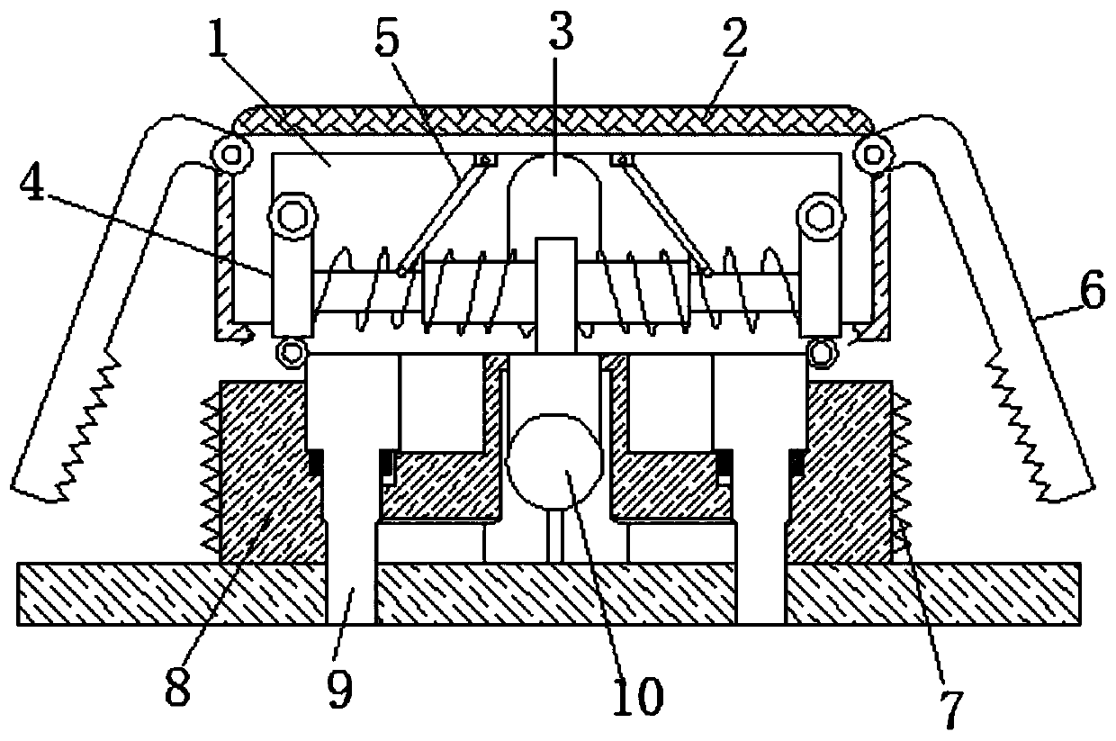
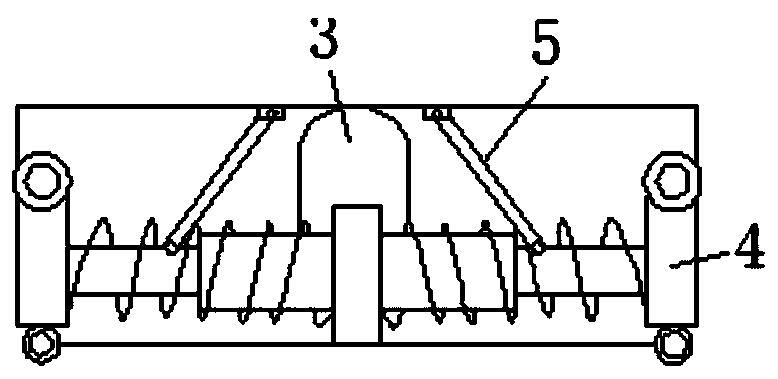
[0022] see Figure 1-5 , an industrial automation and convenient fan installation equipment, including a housing 1, the upper part of the housing 1 is fixedly connected with a placement plate 2, the size of the placement plate 2 is suitable for large, medium and small fan models, so that it can be used more widely, and the placement plate The surface of 2 is fixedly connected with a cooling plate 11. The cooling plate 11 not only plays the role of heat dissipa...


PUM


Abstract

The invention relates to the technical field of fan installation, and discloses an industrial automatic and convenient fan installation device. The industrial automatic and convenient fan installationdevice comprises a shell, a placing plate is fixedly connected to the upper part of the shell, a pressing rod is movably connected to the inside of the shell, the surface of the pressing rod is movably connected with an elastic column, the surface of the elastic column is movably connected to the placing plate through a connecting rod, clamping plates are hinged to the positions, located on the two sides of the elastic column, of the surface of the shell, clamping grooves are movably connected to the surfaces of the clamping plates, and blocking blocks are fixedly connected to the sides, farfrom the clamping plates, of the clamping grooves. Part of vibration is still transmitted to the elastic column inside the shell, the elastic column only shakes left and right when the vibration is received, up and down vibration can be absorbed, the left and right shaking of the elastic column does not affect the connection relationship of the clamping plates and the clamping grooves, and the effect that installation parts are not affected by the vibration of a fan is achieved; and in addition, impurities or debris absorbed during operation of the fan can fall from a flowing outlet to the outside of the shell, and normal operation of connectors cannot be influenced.

Description

technical field [0001] The invention relates to the technical field of fan installation, in particular to an industrial automation and convenient fan installation device. Background technique [0002] The fan is a machine that relies on the input mechanical energy to increase the gas pressure and discharge the gas. It is a driven fluid machine. Fan is the customary abbreviation for gas compression and gas conveying machinery in China. Generally speaking, fans include ventilators, blowers, and wind generators. [0003] As fans are used in more and more places, the disassembly and assembly of fan bases has become particularly important. Because of the high efficiency and convenience of fans, the speed of disassembly and assembly also directly affects their work efficiency. However, there are many fan bases currently in existence. The problem is that on the one hand, the fan will vibrate when it is working, and the small vibration will easily cause the fan and the parts instal...

Claims


Application Information

Patent Timeline
Patent Type & Authority Applications(China)
IPC IPC(8): F04D29/60F04D29/66F04D29/58F03D13/20F03D80/60F16F15/04
CPCF04D29/584F04D29/601F04D29/668F16F15/04F03D13/20F03D80/60Y02E10/72Y02E10/728
Inventor 丁维兵
Owner 绍兴市华获智能装备有限公司
Why Eureka
Try Eureka