Fastening device and fastening method for multi-ridge oscillator antenna

A vibrator antenna and fastening device technology, applied in the direction of antenna support/installation device, antenna, antenna parts, etc., can solve the problems of screw shaking, stress concentration and fracture, etc., to avoid stress concentration, buffer bending stress and concentrated stress Effect

Active Publication Date: 2019-11-22
HUBEI SANJIANG SPACE XIANFENG ELECTRONICS&INFORMATION CO LTD
View PDF8 Cites 2 Cited by
  • Summary
  • Abstract
  • Description
  • Claims
  • Application Information

AI Technical Summary

Problems solved by technology

[0007] Aiming at the above defects or improvement needs of the prior art, the present invention provides a fastening device and fastening method for a multi-ridge dipole antenna. By setting a central support and several peripheral supports arranged symmetrically with respect to the central support, several antenna wide ridges and The narrow ridges of the antenna provide support and preliminary fixation. The peripheral supports arranged symmetrically in pairs are just placed inside the two ends of the wide ridges of the antenna. The ends of the wide ridges and the narrow ridges of the antenna rest on the peripheral supports. Fixed on the peripheral support, the other end is stuck in the groove of the central support to limit and fix. Avoid the use of screws to fix. Avoid the use of countersunk holes and countersunk screws, and solve the problem caused by the narrow ridge width and thickness. Stress concentration breaks, screws cannot be completely sunk into the exposed part, causing assembly interference, and there is a gap in the fixation that causes shaking problems in a vibrating environment; two sets of antennas with wide ridges are arranged in a cross and fixed on the central support and peripheral supports to form a stable support structure

Method used


Image

  • Fastening device and fastening method for multi-ridge oscillator antenna
  • Fastening device and fastening method for multi-ridge oscillator antenna
  • Fastening device and fastening method for multi-ridge oscillator antenna

Examples


Embodiment Construction

[0042] In order to make the object, technical solution and advantages of the present invention clearer, the present invention will be further described in detail below in conjunction with the accompanying drawings and embodiments. It should be understood that the specific embodiments described here are only used to explain the present invention, not to limit the present invention. In addition, the technical features involved in the various embodiments of the present invention described below can be combined with each other as long as they do not constitute a conflict with each other.

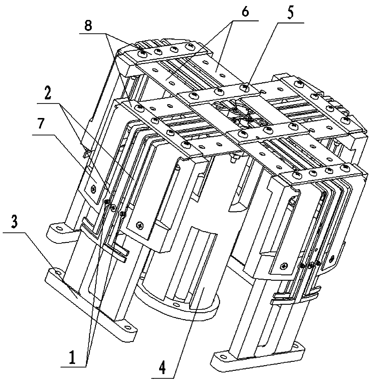
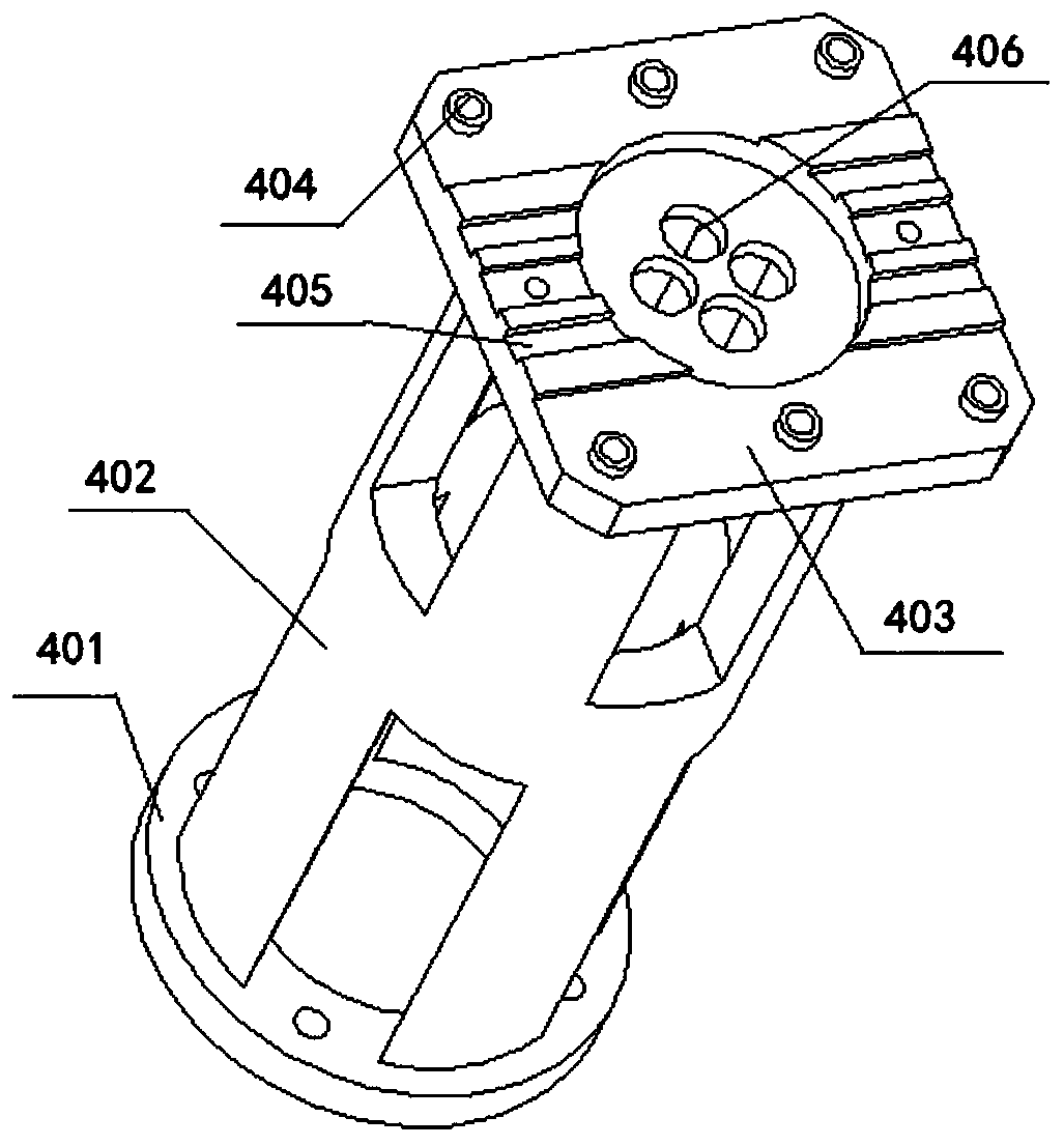
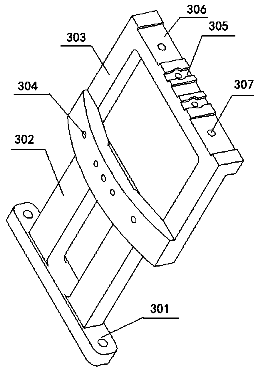
[0043] figure 1 It is a structural schematic diagram of a fastening device for a multi-ridge dipole antenna in an embodiment of the present invention. Such as figure 1 As shown, the multi-ridge antenna includes a narrow antenna ridge and a wide antenna ridge, and the fastening device of the multi-ridge dipole antenna includes a peripheral support 3, a central support 4, a screw 1, a non-metall...


PUM


Abstract

The invention discloses a fastening device of a multi-ridge oscillator antenna. The fastening device comprises a plurality of antenna narrow ridges (2), antenna wide ridges, a central support (4) anda plurality of peripheral supports (3), wherein every two peripheral supports (3) are symmetrically arranged relative to the central support (4); the two groups of antenna wide ridges are arranged onthe central support (4) and the peripheral support (3) in a crossed manner; wherein the antenna narrow ridges (2) are symmetrical about the central support (4) and are placed on the peripheral supports (3), and the top of the central support (4) is provided with central fixing holes (404) corresponding to the intersections of the two groups of antenna wide ridges and second narrow ridge fixing grooves (405) in interference fit with the antenna narrow ridges (2). The invention further discloses a fastening method of the multi-ridge oscillator antenna. According to the fastening device of the multi-ridge oscillator antenna, a large-range screw fixing mode is avoided, and the limiting and fixing effect is good.

Description

technical field [0001] The invention belongs to the technical field of dipole antennas, and more particularly relates to a fastening device and fastening method for various antenna ridges in an interference antenna. Background technique [0002] In the field of dipole antennas, due to different antenna performance requirements, more and more dipole antennas are currently adopting a structure with multiple antenna ridges, and the structure of antenna ridges often has diversity (wide, narrow, thick, thin) , which brings some difficulty to the fastening method of the antenna ridge. [0003] Usually, the method of fixing the antenna ridge is to add countersunk holes on the front of the antenna ridge, the countersunk screws pass through the countersunk holes and non-metallic materials on the ridge, and finally install the spring flat washer nuts on the reverse side. This kind of fixing structure is relatively simple and operable , but this method is feasible under the condition ...

Claims


Application Information

Patent Timeline
Patent Type & Authority Applications(China)
IPC IPC(8): H01Q1/12H01Q1/36
CPCH01Q1/1207H01Q1/36
Inventor 李小猛曾琴琴喻昆仑
Owner HUBEI SANJIANG SPACE XIANFENG ELECTRONICS&INFORMATION CO LTD
Why Eureka
Try Eureka