
Power tube driving circuit and driving method

A driving circuit and driving method technology, which are applied in output power conversion devices, DC power input conversion to DC power output, electrical components, etc., can solve the breakdown of synchronous rectification power tubes, large leakage inductance energy, and leakage inductance spike voltage. higher question

Pending Publication Date: 2019-11-22
ANHUI DONGKE SEMICON CO LTD
View PDF0 Cites 7 Cited by
  • Summary
  • Abstract
  • Description
  • Claims
  • Application Information

AI Technical Summary

Problems solved by technology

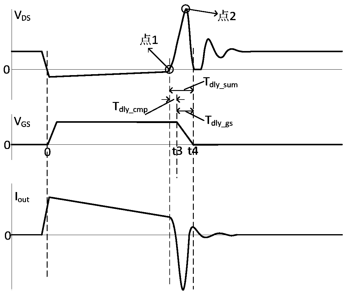
Especially in continuous current mode (CCM), if the leakage inductance energy is large if the shutdown is not timely, the resulting leakage inductance peak voltage is very high (such as figure 2 Point 2), exceeding the collapse voltage of the synchronous rectification power tube will cause the breakdown of the synchronous rectification power tube and cause damage to the system

Method used


Image

  • Power tube driving circuit and driving method
  • Power tube driving circuit and driving method
  • Power tube driving circuit and driving method

Examples


Embodiment Construction

[0042] Exemplary embodiments of the present disclosure will be described below with reference to the accompanying drawings. In the interest of clarity and conciseness, not all features of an actual implementation are described in this specification. It should be understood, however, that many implementation-specific decisions can be made in developing any such actual implementation in order to achieve the developer's specific goals, and that these decisions may vary from implementation to implementation .

[0043] Here, it needs to be noted that, in order to avoid obscuring the present disclosure due to unnecessary details, only the device structure closely related to the solution according to the present disclosure is shown in the drawings, and the structure related to the present disclosure is omitted. Other details that are not relevant to the disclosure.

[0044] It is to be understood that the present disclosure is not limited to only the described embodiments as descri...


PUM


Abstract

The invention provides a power tube driving circuit and a driving method, and relates to the field of power electronic conversion. Before the power tube is turned off, partial charges of a grid electrode of the power tube are discharged in advance through a pre-closing process, so that the power tube is turned off, wherein the starting moment of the pre-closing in the next period is adaptively adjusted through the time interval between the ending moment of the pre-closing in the current period and the turning-off moment of the power tube. Smooth starting and ending of pre-closing can be effectively guaranteed by adjusting the starting moment of pre-closing in a self-adaptive mode, especially when the method is applied to driving of a synchronous rectification power tube, it can be guaranteed that the starting moment and the ending moment of pre-closing can be adjusted in the self-adaptive mode at DCM, CCM and even depth CCM, and smooth starting and ending of pre-closing are guaranteed.

Description

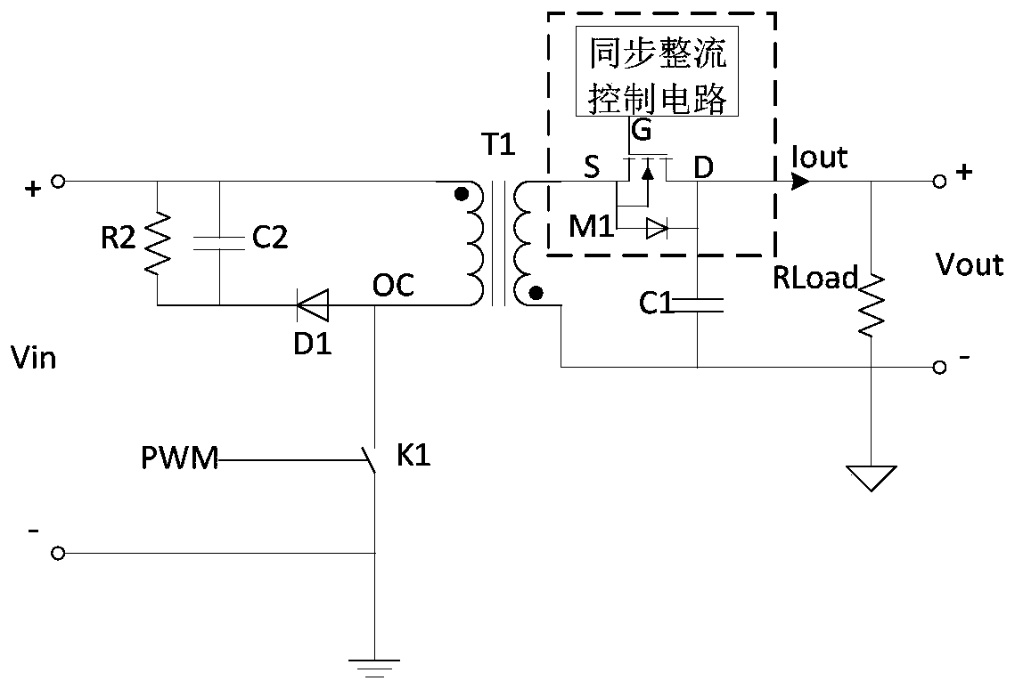
technical field [0001] The invention relates to the field of power electronic conversion, and more specifically, to a power tube drive circuit and a drive method. Background technique [0002] With the development of electronic technology, power transistors are used more and more as switching elements in circuits. However, in application circuits such as synchronous rectification, power tubes always have the problem of too slow turn-off speed. If the gate charge Qg that needs to be discharged to turn off the power tube is more, the gate (G) of the power tube to the source (S) voltage V GS The longer the transition time to 0V, the slower the power tube turns off. [0003] If the turn-off speed of the power tube is too slow, it will have a bad impact on the circuit where it is located, especially in such figure 1 In the common flyback synchronous rectification circuit shown. figure 2 shows the same figure 1 Corresponding working waveform diagram, by figure 2 It can be ...

Claims


Application Information

Patent Timeline
Patent Type & Authority Applications(China)
IPC IPC(8): H02M1/08H02M3/335H02M1/32
CPCH02M1/08H02M3/33523H02M1/32Y02B70/10
Inventor 谢勇程兆辉于玮
Owner ANHUI DONGKE SEMICON CO LTD
Learn More