Method and device for controlling a capacitive load

A capacitive load, load current technology, applied in the direction of generator/motor, piezoelectric device or electrostrictive device parts, piezoelectric effect/electrostrictive or magnetostrictive motor, etc., can solve the problem of creep. Electrical effects, nonlinear polarization, losses, etc., to achieve the effect of improving accuracy, reducing oscillation tendency, and accurate detection

Active Publication Date: 2008-08-27
VTESCO TECH GMBH
View PDF3 Cites 6 Cited by
  • Summary
  • Abstract
  • Description
  • Claims
  • Application Information

AI Technical Summary

Problems solved by technology

In addition, many capacitive loads actually have variable large-signal capacity or non-linearity, which makes it difficult to define the curve of energy input or energy output particularly accurately, and has the effect of amplifying the oscillation effect mentioned above or Tendency to say and complicate transition oscillation effects
If the capacitive load in question is a piezo stack, then in addition to the non-linearity there will actually be polarization losses, creepage effects, etc.

Method used


Image

  • Method and device for controlling a capacitive load
  • Method and device for controlling a capacitive load

Examples


Embodiment Construction

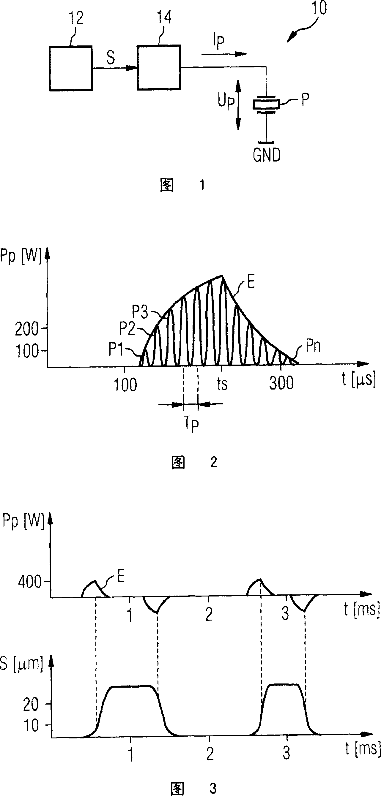
[0044] FIG. 1 shows a block diagram of a circuit 10 for triggering a piezo actuator P connected to an output stage 14 of the circuit 10 . The output stage 14 supplies a current Ip for charging or discharging the piezoelectric actuator P.

[0045] The output stage 14 can be configured as a conventional switching converter or as a Buck-Boost converter, as a Flyback converter or as a SEPIC converter, and depends on a control signal S (such as one or more control voltages) to provide current, the control signal is issued by the control unit 12 of the circuit 10 on the basis of a trigger setpoint and taking into account measured variables within the range of the output stage 14 and / or within the It can be determined within the range of the piezoelectric actuator P described above (for example, the piezoelectric voltage Up and / or the piezoelectric current Ip).

[0046] The circuit 10 forms part of a so-called engine control unit for an internal combustion engine and is used to trig...


PUM


Abstract

The aim of the invention is to avoid a tendency of the controlled load to oscillate when controlling a capacitive load, in particular, of a piezo actuator for an injection valve of an internal combustion engine, having charging and discharging processes for charging and discharging the capacitive load by means of a load current, each loading process being effected by chronological partial load current pulses according to chronological partial charging capacity pulses (p1, p2, ... pn). To this end, the invention provides that the envelope (E) of the partial charging capacity pulses (p1, p2, ... pn), during the loading process, increases in a strictly monotonous manner in an initial phase, and the slope of the envelope decreases in a monotonous manner.

Description

technical field [0001] The invention relates to a method for activating a capacitive load, in particular for activating a piezoelectric actuator for an injection valve of an internal combustion engine, according to the preamble of claim 1 . Furthermore, the invention relates to a device for carrying out such a triggering method. Background technique [0002] Such methods and devices are known, for example, from DE 199 44 733 A1, DE 198 14 594 A1 and DE 199 52 950 A1. [0003] Especially in the automotive industry, increasingly stringent engine emission standards have recently promoted the development of fuel injectors with fast and undelayed-responsive actuators or actuators. In the actual realization of the actuator, piezoelectric elements (piezo actuators for short) in particular have proven to be very advantageous. The piezo elements are usually combined to form a stack of piezoceramic disks, which are operated in a parallel circuit in order to be able to achieve the el...

Claims


Application Information

Patent Timeline
Patent Type & Authority Applications(China)
IPC IPC(8): F02D41/20H01L41/04
CPCH01L41/042F02D41/2096F02D2041/2034H02N2/067H10N30/802
Inventor C·豪瑟K·基尔M·克拉梅尔H·利克斯尔G·马扎恩W·施罗德
Owner VTESCO TECH GMBH
Why Eureka
Try Eureka