Gas discharging connector

A technology for deflation joints and deflation valves, which is applied in the direction of non-mechanical drive clutches, fluid drive clutches, clutches, etc., can solve problems such as leakage of the deflation valve body and joint housing, and reduce the degree of correlation and leakage risk effect

Inactive Publication Date: 2012-11-14
SCHAEFFLER TECH AG & CO KG
View PDF5 Cites 6 Cited by
  • Summary
  • Abstract
  • Description
  • Claims
  • Application Information

AI Technical Summary

Problems solved by technology

But since in this fitting the hose seal creates a face seal, when the two holes in the fitting housing (the small hole for the hose seal and the large hole for the bleed valve body) When the roundness and coaxiality of the valve are poor, especially after a strong temperature change (working temperature is 150 degrees to minus 40 degrees), the bleed valve body is inclined relative to the joint housing
This can cause leakage between the bleed valve body and the fitting housing

Method used


Image

  • Gas discharging connector
  • Gas discharging connector
  • Gas discharging connector

Examples


Embodiment Construction

[0021] Embodiments of the present invention are described in detail below with reference to FIGS. 3-5 .

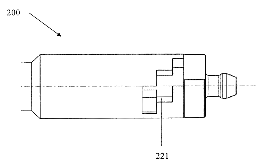
[0022] Figure 3A -B and Figure 4A -B shows the bleed joint 200 of the present invention for the vehicle hydraulic clutch separation system, which includes a bleed valve body 210 and a joint housing 220, the bleed valve body 210 is assembled in the joint housing 220, and can be opposite to the joint The housing 220 rotates, a main seal 230 is installed between the deflation valve body 210 and the joint housing 220, and the deflation valve body 210 has a hole 211 on its outer periphery, and the hole 211 can be main sealed The member 230 is closed and can be opened after being rotated 180 degrees for discharge. The joint 200 also has an auxiliary seal 240 installed between the deflation valve body 210 and the joint housing 220 behind the hole 211 in the discharge direction.

[0023] In an embodiment, the purge valve body 210 includes a large diameter portion and a small ...


PUM


Abstract

The invention provides a gas discharging connector (200; 300) for filling liquid and discharging gas in a hydraulic clutch separation system of a vehicle, which comprises a gas discharging valve body (210; 310) and a connector shell (220; 340). The gas discharging valve body (210; 310) is arranged in the connector shell (220; 340), can rotate and is provided with a main sealing component (230; 330). Moreover, the gas discharging valve body (210; 310) is internally provided with a hole (211; 311), the hole is sealed by the main sealing component (230; 330) and can be operated after being rotated for 180 degrees so as to discharge air or liquid in the system as needed. The gas discharging connector (200; 300) is also provided with an auxiliary sealing component (240; 350), the auxiliary sealing component is arranged on the gas discharging valve body (210; 310) and on the hole along the discharging direction to reduce the inclination of the gas discharging valve body relative to the connector shell so as to reduce the risk of leakage between the gas discharging valve body and the connector shell.

Description

technical field [0001] The application relates to a vehicle hydraulic clutch release system, in particular to an air release joint used for liquid filling and exhaust in the vehicle hydraulic clutch release system. Background technique [0002] In the prior art, the release of the air release valve body in the hydraulic clutch separation system usually adopts the following two methods. One is a threaded vent connector. Such as Figures 1A-1B As shown, the threaded deflation joint 100 is composed of only two components, the deflation valve body 110 and the joint housing 120 , which are fixed together by the threads 112 on the deflation valve body 110 and the joint housing 120 . In this way, when the threaded fastening is loosened and thus the hole 111 in the purge valve body 110 is opened, the threaded fastening acts as an auxiliary seal preventing leakage between the joint housing 120 and the purge valve body 110 . There is also an inclined surface 113 in the deflation val...

Claims


Application Information

Patent Timeline
Patent Type & Authority Applications(China)
IPC IPC(8): F16D25/12
CPCF16D2300/12F16D25/083
Inventor 黄超
Owner SCHAEFFLER TECH AG & CO KG
Why Eureka
Try Eureka