
Electronic device

A technology for electronic equipment and fans, which is applied in the structural parts of electrical equipment, electrical components, cooling/ventilation/heating transformation, etc. It can solve the problems of high temperature of electronic equipment and affect user experience, so as to improve heat dissipation efficiency, reduce temperature, The effect of improving user experience

Inactive Publication Date: 2019-11-22
LENOVO (BEIJING) LTD
View PDF5 Cites 6 Cited by
  • Summary
  • Abstract
  • Description
  • Claims
  • Application Information

AI Technical Summary

Problems solved by technology

However, the electronic devices in the prior art are designed to be thinner and thinner, and the heat on the surface of the functional components will directly cause the temperature of the electronic device to be higher, affecting user experience.

Method used


Image

  • Electronic device
  • Electronic device
  • Electronic device

Examples


example 1

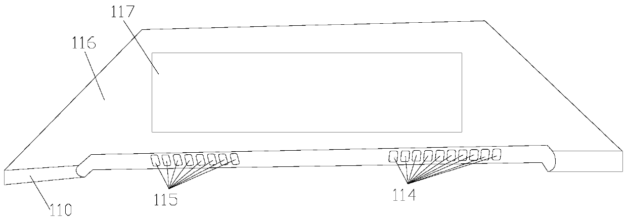
[0076] Example 1, such as image 3 As shown, the air inlet includes: a first air inlet. The first air inlet is located in the first sub-second area 117 of the front surface 116, and the projection of the fan 120 on the front surface 116 forms a first sub-first area, and the first sub-first area is connected to the first sub-first area. The first part of the sub-second area 117 overlaps; that is, the first sub-first area is located within the first sub-second area 117 .

[0077] Here, the structure of the first air inlet is not limited.

[0078] For example, the first air inlet includes a plurality of through holes that may be disposed in the first sub-second area 117 .

[0079] Another example, such as Figure 4 As shown, the electronic device may further include: a first component 160 . The first component 160 is arranged on the front surface 116 of the housing 110; the front surface 116 of the housing 110 is provided with an opening 113, the first component 160 is arrang...

example 2

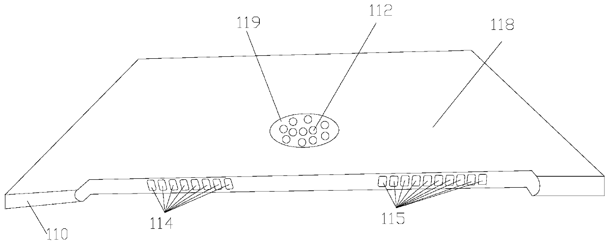
[0082] Example 2, such as figure 2 As shown, the air inlet may include: a second air inlet 112 . The second air inlet 112 is located in the second sub-second area 119 of the back 118; the projection of the fan 120 on the back 118 forms a second sub-first area; The two sub-second regions 119 overlap.

[0083] Here, the structure of the second air inlet 112 is not limited. For example, if figure 2 As shown, the second air inlet 112 includes a plurality of through holes that may be disposed in the second sub-second area 119 .

[0084] Certainly, the electronic device may include the first air inlet and the second air inlet 112 at the same time.

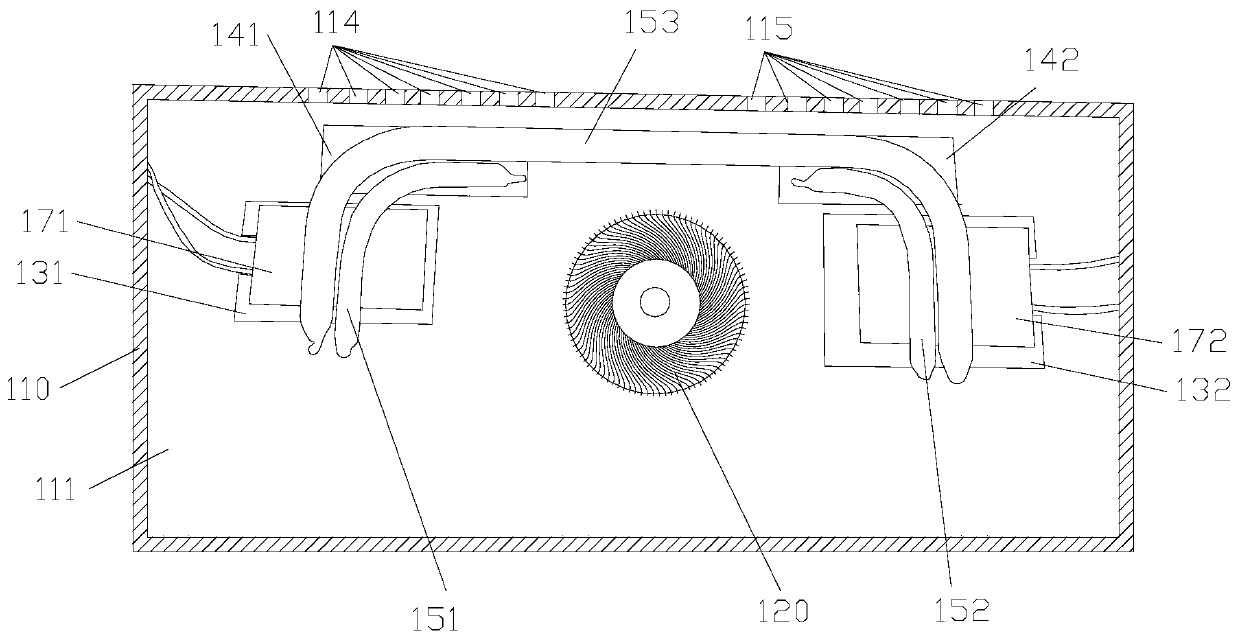
[0085] In some optional implementation manners of the embodiment of the present application, the air outlet may include: a first air outlet 114 and a second air outlet 115 . The first air outlet 114 is located on the side of the housing 110; the second air outlet 115 is located on the side of the housing 110; so that the fan 120 g...


PUM


Abstract

The embodiment of the invention discloses electronic device. The electronic device comprises: a shell provided with a containing cavity and provided with an air inlet and an air outlet; a fan that isarranged in the containing cavity; a functional assembly that is arranged in the containing cavity; a heat dissipation assembly that is arranged in the containing cavity and is used for dissipating heat of the functional assembly; the fan can suck air from the air inlet, so that the air is blown to the functional assembly in a first direction and blown to the heat dissipation assembly in a seconddirection, and the air subjected to heat exchange with the functional assembly and the heat dissipation assembly is guided out of the air outlet; the first direction is different from the second direction. According to the electronic device provided by the embodiment of the invention, heat on the surface of the functional assembly can be directly taken away through the fan, and the temperature ofthe surface of the functional assembly is effectively reduced, so that the temperature of the electronic device is effectively reduced.

Description

technical field [0001] The embodiment of the present application relates to an electronic device. Background technique [0002] Electronic equipment is often used by people. Electronic equipment generally includes a housing, a functional component and a heat dissipation component disposed in an accommodating cavity of the housing; and the heat dissipation component dissipates heat for the functional component. However, the electronic devices in the prior art are designed to be thinner and thinner, and the heat on the surface of the functional components will directly lead to a higher temperature of the electronic device, affecting user experience. Contents of the invention [0003] The embodiments of the present application provide an electronic device to solve the problems existing in the prior art. [0004] The technical scheme of the embodiment of the application is realized in this way: [0005] An embodiment of the present application provides an electronic device, ...

Claims


Application Information

Patent Timeline
Patent Type & Authority Applications(China)
IPC IPC(8): H05K7/20
CPCH05K7/20136
Inventor 李自然
Owner LENOVO (BEIJING) LTD
Learn More