Novel magnetic control lock catch for restraint strap

A technology of restraint belt and magnetic control lock, which is applied in the field of locks, can solve the problems of cumbersome operation, affecting the recovery of patients, affecting the effect of patients' surgery, etc., and achieves the effect of simple operation, saving operation steps and time, and novel structural design

Pending Publication Date: 2019-11-26
东莞市蒙泰护理用品有限公司 +1
View PDF0 Cites 6 Cited by
  • Summary
  • Abstract
  • Description
  • Claims
  • Application Information

AI Technical Summary

Problems solved by technology

[0002] Patients are prone to irritability and uncontrolled anesthesia reactions during and after anesthesia, and protective restraint is required, otherwise it will not only affect the surgical effect of the patient, but also seriously affect the recovery of the patient; in the treatment of patients with mental symptoms When using a restraint belt, the patient needs to be restrained protectively to prevent accidental injuries such as self-harm, self-injury, falling from the bed, bedside scratches, etc., and at the same time ensure the smooth progress of the treatment. The magnetically controlled lock is locked and fixed. When the existing magnetically controlled lock is practical, the magnet must first be adsorbed on the lock body to absorb the positioning pin in the lock body before inserting the lock tongue. Insert the lock tongue into a suitable position and then insert it. The magnet is detached from the lock body, and the positioning pin in the lock body is then inserted into the lock tongue to lock it. This operation is cumbersome, and the patient cannot be restrained in time when an emergency occurs.

Method used


Image

  • Novel magnetic control lock catch for restraint strap
  • Novel magnetic control lock catch for restraint strap
  • Novel magnetic control lock catch for restraint strap

Examples


specific Embodiment 1

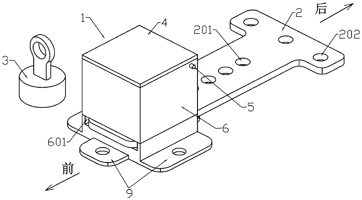
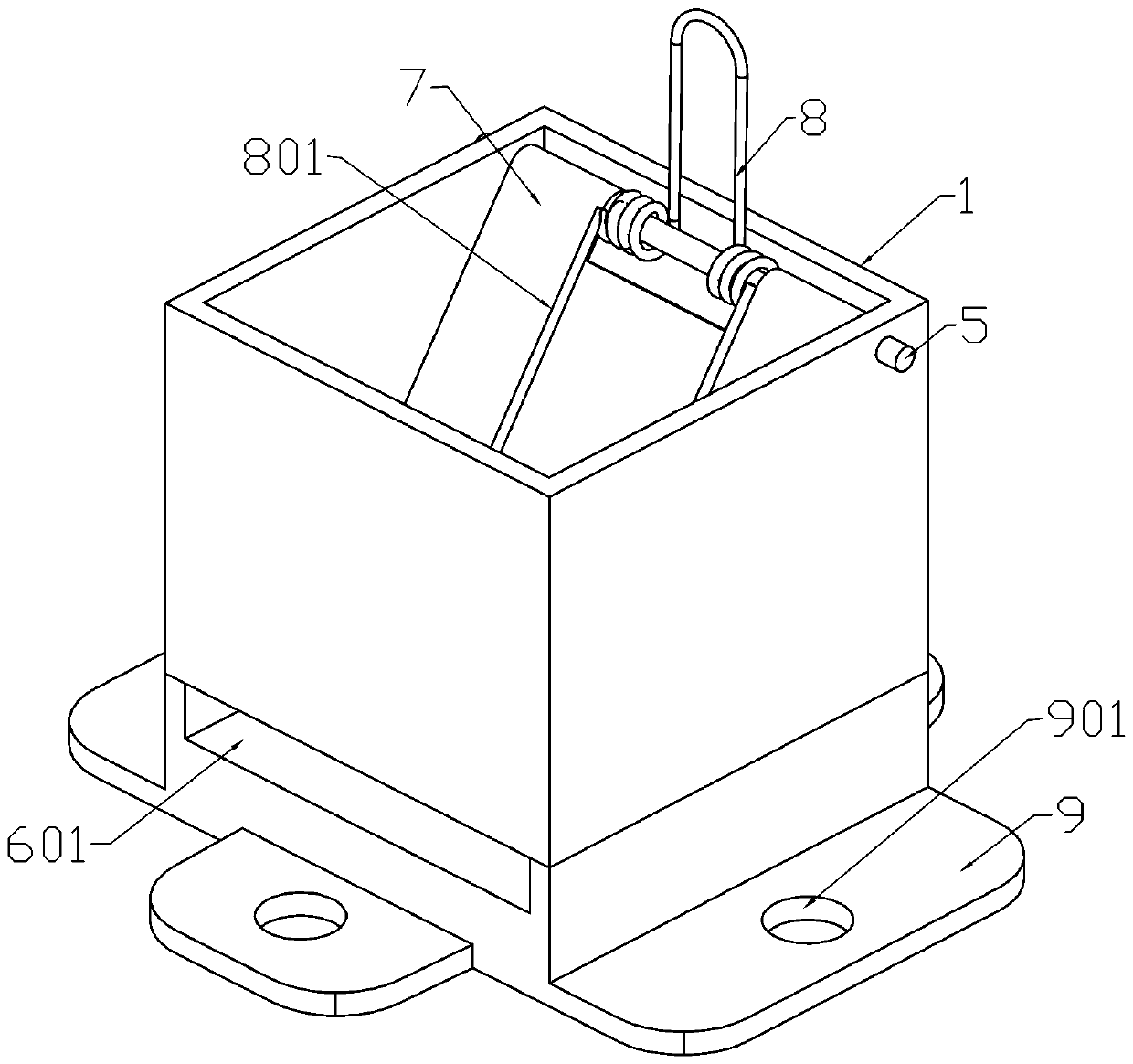
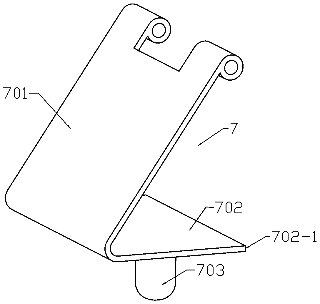
[0018] Specific Example 1: See Figure 1 to Figure 5 , in an embodiment of the present invention, a new type of magnetically controlled lock for restraint belts, including a lock body 1, a lock tongue 2 and a magnet 3, the lock body 1 and the lock tongue 2 are generally made of metal materials, and the lock body 1 Comprising a lock body frame 6 and a positioning frame 7, the positioning frame 7 is connected to one side of the lock body frame 6 by rotating shaft 5, and the two ends of the rotating shaft 5 are respectively fixed on the left and right sides in the lock body frame 6, A reset member 8 is provided between the positioning frame 7 and the rotating shaft 5, a positioning column 703 is provided at the bottom of the positioning frame 7, and a jack 601 is provided at the bottom of the lock body frame 6, and the jack 601 runs through The front and rear sides of the lock body frame 6; several positioning holes 201 are arranged side by side on the dead bolt 2, and the dead b...


PUM


Abstract

The invention provides a novel magnetic control lock catch for a restraint strap. The novel magnetic control lock catch comprises a lock body, a spring bolt and a magnet; the lock body comprises a lock body frame and a positioning frame; the positioning frame is rotationally connected into the lock body frame through a rotating shaft; the two ends of the rotating shaft are fixed to the left side and the right side in the lock body frame; a reset piece is arranged between the positioning frame and the rotating shaft; a positioning column is arranged at the bottom of the positioning frame; an insertion hole is formed in the bottom end of the lock body frame; the insertion hole penetrates through the front side and the rear side of the lock body frame; a plurality of positioning holes are formed in the spring bolt side by side; the spring bolt is horizontally inserted into the insertion hole from the rear side of the lock body frame; and the spring bolt pushes the positioning column forwards in the insertion hole to enable the positioning column to be correspondingly inserted into the positioning hole. According to the novel magnetic control lock catch for the constraint belt, the spring bolt can be directly inserted into the lock body from the insertion hole in the right side of the lock body and is pushed forwards to a proper position for locking; the magnet does not need to beused additionally for unlocking; and the operation is simple, and the operation steps and time are saved.

Description

technical field [0001] The invention relates to the technical field of locks, in particular to a novel magnetically controlled lock for restraint belts. Background technique [0002] Patients are prone to irritability and uncontrolled anesthesia reactions during and after anesthesia, and protective restraint is required, otherwise it will not only affect the surgical effect of the patient, but also seriously affect the recovery of the patient; in the treatment of patients with mental symptoms When using a restraint belt, the patient needs to be restrained protectively to prevent accidental injuries such as self-harm, self-injury, falling from the bed, bedside scratches, etc., and at the same time ensure the smooth progress of the treatment. The magnetically controlled lock is locked and fixed. When the existing magnetically controlled lock is practical, the magnet must first be adsorbed on the lock body to absorb the positioning pin in the lock body before inserting the lock...

Claims


Application Information

Patent Timeline
Patent Type & Authority Applications(China)
IPC IPC(8): A44B11/25
CPCA44B11/2503A44B11/2546
Inventor 曾辉章刘锡川陈仁英
Owner 东莞市蒙泰护理用品有限公司
Why Eureka
Try Eureka