
Punching die for laser welding surfaces of side plate of backrest of automobile and processing method thereof

A laser welding and stamping die technology, applied in the field of auto parts shaping, can solve the problems of uneven laser welding surface, wear and increase of the shaping drive device, unbalanced force on the die, etc., achieve high rigidity strength, improve shaping stability, The effect of easy debugging

Pending Publication Date: 2019-11-26
深圳数码模汽车技术有限公司
View PDF0 Cites 1 Cited by
  • Summary
  • Abstract
  • Description
  • Claims
  • Application Information

AI Technical Summary

Problems solved by technology

[0002] In the car seat frame series parts, the seat side plate parts are very important in the whole seat series parts. When the side plate is welded with the upper cross beam and the lower cross beam on the same laser welding surface, welding weld penetration often occurs, and welding defects Welding, the welding of the two products is not equal, and the above results are usually caused by the unevenness of the laser welding surface, because the two sides of the head and tail of the side plate are laser welding surfaces, according to the normal design plan, it will be considered to be separated for easy adjustment, and the mold The space is large, but the size of the other side will change after one side is adjusted during the shaping process, and the uneven force on one side often leads to wear and block of the shaping drive device, and the force of the whole mold is not balanced, etc.

Method used


Image

  • Punching die for laser welding surfaces of side plate of backrest of automobile and processing method thereof
  • Punching die for laser welding surfaces of side plate of backrest of automobile and processing method thereof
  • Punching die for laser welding surfaces of side plate of backrest of automobile and processing method thereof

Examples


Embodiment Construction

[0024] In order to make the purpose, technical solutions and advantages of the embodiments of the present invention clearer, a clear and complete description will be made below in conjunction with the technical solutions in the embodiments of the present invention. Obviously, the described embodiments are part of the embodiments of the present invention, and Not all examples. Based on the embodiments of the present invention, all other embodiments obtained by persons of ordinary skill in the art without making creative efforts belong to the protection scope of the present invention.

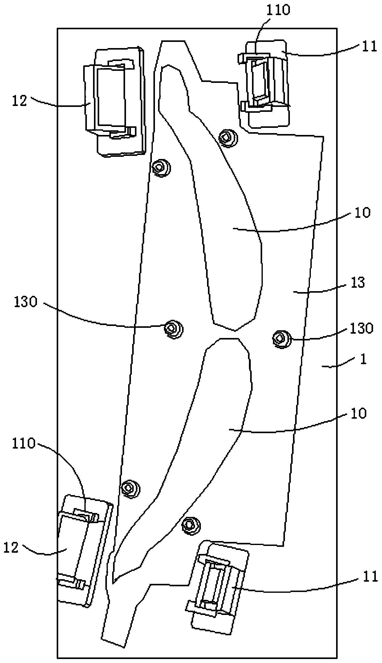
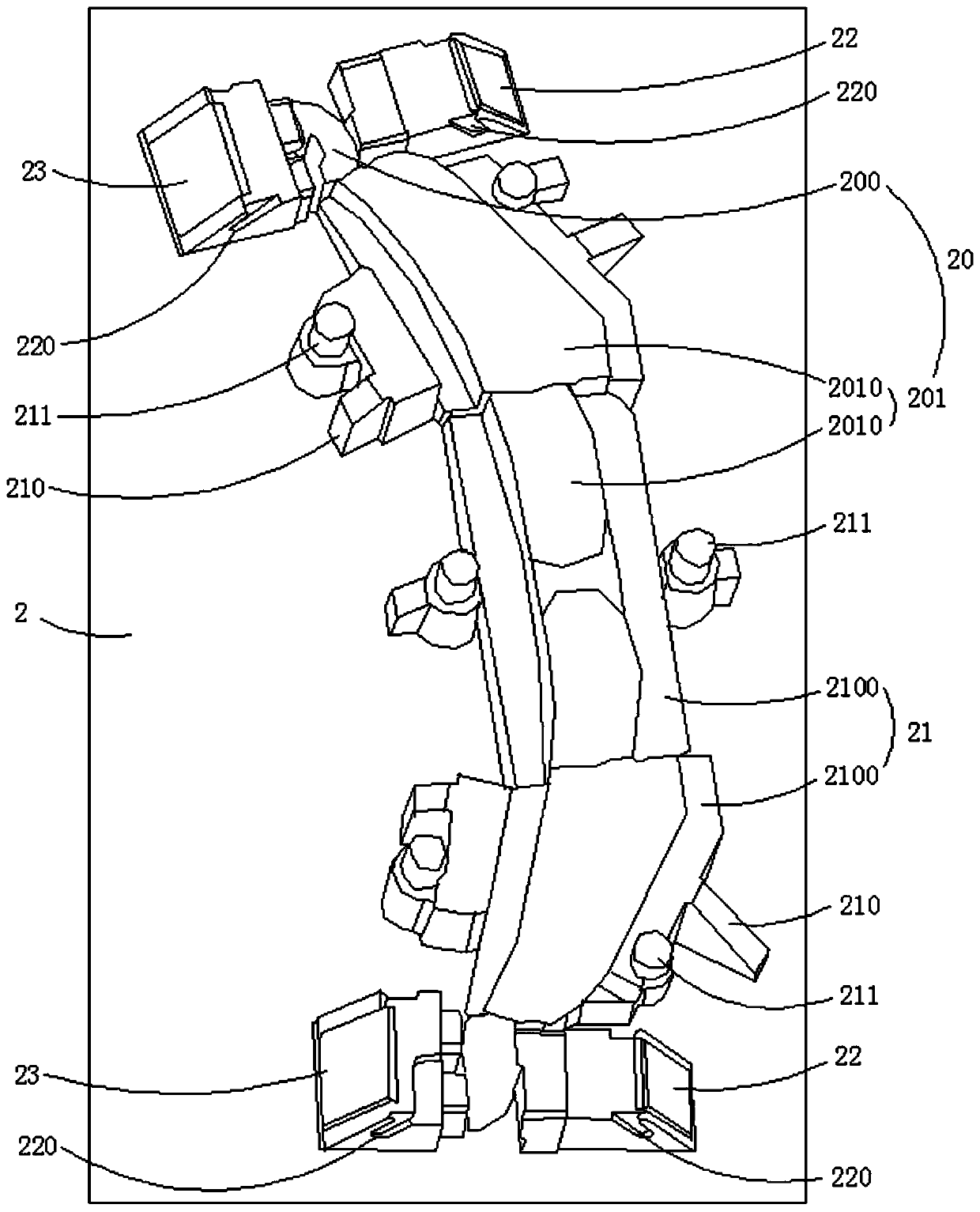
[0025] The stamping die of the laser welding surface of the automobile backrest side plate of the preferred embodiment of the present invention, such as figure 1 shown, see also figure 2 , including an upper template 1 and a lower template 2; the lower template 2 is provided with a profiling positioning block 20, and the profiling positioning block 20 includes a first positioning block 200 that...


PUM


Abstract

The invention relates to a punching die for laser welding surfaces of a side plate of a backrest of an automobile. The punching die comprises an upper die plate and a lower die plate. A copy positioning block is arranged on the lower die plate and comprises a first positioning block and a second positioning block; two auxiliary holding blocks are detachably arranged on the lower die plate and a first side shaping block and a second side shaping block are slidably arranged on the lower die plate; first shaping concave dies corresponding to the first side shaping block and second shaping concavedies corresponding to the second side shaping blocks are separately arranged on two sides of the first positioning block; an integrated copy limiting block matched with the copy positioning block, afirst driving block driving the first side shaping block and a second driving block driving the second side shaping block are fixedly arranged on the upper die plate; meanwhile, the laser welding surfaces at two ends of the side plate are held synchronously and relatively high rigid strength can be kept without conventional swaging and shaping. The laser welding surfaces are no longer affected bysecondary swaging deformation of a swaging plate, so that the shaping stability is improved.

Description

technical field [0001] The invention relates to the technical field of auto parts shaping, and more specifically relates to a stamping die for a laser welding surface of an automobile backrest side plate and a processing method thereof. Background technique [0002] In the car seat frame series parts, the seat side plate parts are very important in the whole seat series parts. When the side plate is welded with the upper cross beam and the lower cross beam on the same laser welding surface, welding weld penetration often occurs, and welding defects Welding, the welding of the two products is not equal, and the above results are usually caused by the unevenness of the laser welding surface, because the two sides of the head and tail of the side plate are laser welding surfaces, according to the normal design plan, it will be considered to be separated for easy adjustment, and the mold The space is large, but the size of the other side will change after one side is adjusted du...

Claims


Application Information

Patent Timeline
Patent Type & Authority Applications(China)
IPC IPC(8): B21D1/10B21D37/10B21D43/00
CPCB21D1/10B21D37/10B21D43/003
Inventor 李愉愉谢茂春吴艺范堡清
Owner 深圳数码模汽车技术有限公司
Features
  • Generate Ideas
  • Intellectual Property
  • Life Sciences
  • Materials
  • Tech Scout
  • Unparalleled Data Quality
  • Higher Quality Content
  • 60% Fewer Hallucinations
Learn More