
A welding device and welding method for capstan and support shaft of pepper removal machine

A technology for welding devices and supporting shafts, which is applied in welding equipment, auxiliary devices, tin feeding devices, etc., and can solve problems such as increased radial load of bearings, damage to the cutter and roller, and overload of the motor.

Active Publication Date: 2021-01-22
ANYANG INST OF TECH
View PDF9 Cites 0 Cited by
  • Summary
  • Abstract
  • Description
  • Claims
  • Application Information

AI Technical Summary

Problems solved by technology

[0003] Most of the current end cover welding support shafts are manually welded, and the coaxiality between the support shaft and the end cover is low. The end cover is fixed at the end of the drum and is coaxial with the drum. The cutting blade is tangent to the outer cylindrical surface of the drum, and the drum rotates. When there is eccentricity, when the cutter cuts the drum pepper, the cutter may not be tangent to the drum, and the handle is not completely removed, or the blade of the cutter cuts into the drum, causing the motor to overload, burning the motor, and damaging the drum of the cutter. In addition, the support When the shaft and the end cover are welded, because the support shaft is not restrained, the welding stress makes the support shaft and the drum not parallel, the drum rotates loudly, the radial load on the bearing increases, and the support shaft and the end cover are prone to fracture due to welding

Method used


Image

  • A welding device and welding method for capstan and support shaft of pepper removal machine
  • A welding device and welding method for capstan and support shaft of pepper removal machine
  • A welding device and welding method for capstan and support shaft of pepper removal machine

Examples


Embodiment Construction

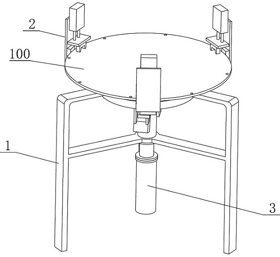
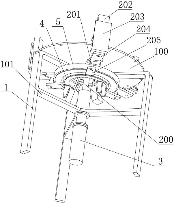
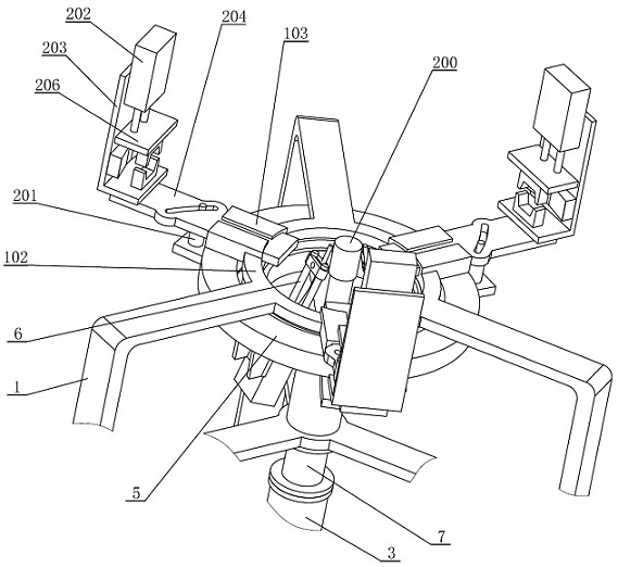
[0049] combine Figure 1-10 , a kind of capsicum of the present invention removes the welding device of machine end cover and support shaft, comprises support frame 1, end cover clamping mechanism 2, support shaft cylinder 3, inner turntable 4, outer turntable 5, welding mechanism 6, connecting sleeve 7. The guide support sleeve 8 is defined as the inner side toward the center of the end cover 100 and the outer side if it is opposite, so as to describe the present application. The end cover clamping mechanism 2 includes a guide pin 201, a compression cylinder 202, a compression frame 203, a sliding plate 204, a fixed support plate 205, an upper compression plate 206, a lower compression block 207, and an upper compression block 208. , side V-shaped block 209, limit key 210, hinge shaft 211, the welding mechanism 6 includes a welding support seat 601, a welding cylinder 602, a welding torch 603, and a welding torch fixing block 604.

[0050] The upper end of the support frame ...


PUM

PropertyMeasurementUnit
angleaaaaaaaaaa

Abstract

The invention discloses a welding device for an end cover and a supporting shaft of a pepper pedicle removing machine. The welding device includes a support frame, the support frame is provided with three end cover clamping mechanisms which are evenly distributed in the circumferential direction, and each end cover clamping mechanism includes a sliding plate, wherein the sliding plate is slidinglyconnected to the upper end of the support frame; the support frame coaxially fixes an inner layer rotary table and an outer layer rotary table, the inner layer rotary table fixes a guide pin, the guide pin is slidably connected with a slide groove in the sliding plate, the slide groove is a chute, the outer end of each sliding plate is fixedly provided with a compression frame, each compression frame is provided with an upper compression block, a lower compression block and a side V-shaped block and is used for centering and clamping the end cover, and the support frame is fixedly provided with a support sleeve and a support shaft cylinder, the supporting shaft is in sliding clearance fit with the support sleeve, the support shaft cylinder is used for tightening the supporting shaft fromthe lower side, and positioning and clamping of the supporting shaft are achieved; and the inner rotary table is fixedly provided with a welding mechanism which is used for welding the end cover and the support shaft, automatic welding of the end cover and the support shaft is achieved, and the coaxiality of the end cover and the support shaft is achieved.

Description

technical field [0001] The invention relates to the field of capsicum removing machine welding equipment, in particular to a welding device and a welding method for a capsicum removing machine end cover and a support shaft. Background technique [0002] Pepper is an important condiment in the catering industry. Before the chili is made into the condiment, it needs to be removed. The chili remover improves the efficiency of removal. The pepper stalks on the frame are cut off, and both ends of the frame need to be supported. At least one end of the frame is supported by a fixed shaft at the geometric center of the end cover, and a gap is provided on the end cover at the other end for feeding or discharging. And the patent: A pepper removal machine (CN201720064323.6), which discloses the use of a cutter to cut off the peppers protruding from the drum. The two ends of the drum are supported by the outer cylinder of the drum. One end cover has a discharge port, so it is difficul...

Claims


Application Information

Patent Timeline
Patent Type & Authority Patents(China)
IPC IPC(8): B23K1/00B23K3/06B23K3/08
CPCB23K1/0008B23K3/063B23K3/087
Inventor 张天鹏郭丽霞范秋凤郭汝静翟亚芳
Owner ANYANG INST OF TECH
Learn More