

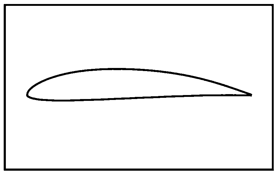
High lift-drag ratio laminar flow aerofoil profile suitable for low altitude and low speed unmanned aerial vehicle
A high-lift-to-drag ratio, unmanned aerial vehicle technology, applied in the direction of the wing shape, can solve the problems of stall characteristics and poor lift-drag characteristics, increase the empty weight of the wing and the whole machine, and less laminar airfoil design, so as to achieve stall Smooth characteristics, excellent torque characteristics, and improved stall characteristics
- Summary
- Abstract
- Description
- Claims
- Application Information
AI Technical Summary
Problems solved by technology
Method used
Image

Examples
Embodiment Construction
[0048] In order to make the technical problems, technical solutions and beneficial effects solved by the present invention clearer, the present invention will be further described in detail below in conjunction with the accompanying drawings and embodiments, wherein the embodiments include theoretical calculation analysis and actual flight tests. It should be understood that the specific embodiments described here are only used to explain the present invention, not to limit the present invention, and the detailed description is as follows.
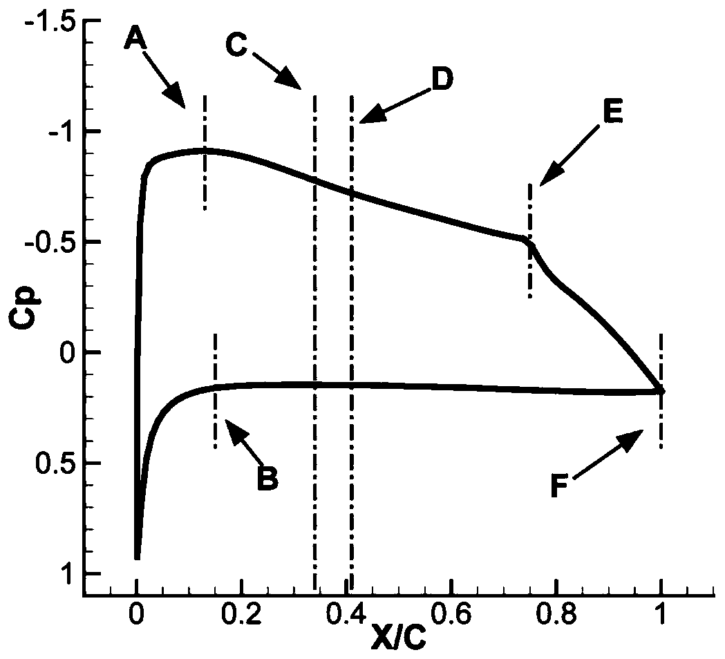
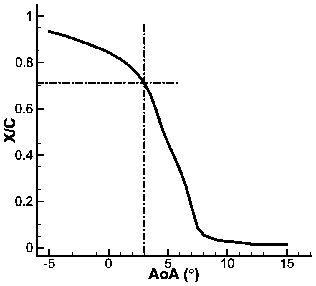
[0049]Under the condition of low Reynolds number, the surface laminar flow separation phenomenon of the conventional airfoil is serious, the lift-drag characteristics of the airfoil are seriously deteriorated, and in the state of high lift, it has a large nose-down moment; while the laminar airfoil has a large The range of laminar flow leads to a large reverse pressure gradient in the tail pressure recovery, which is easy to cause separatio...
PUM
 Abstract
Description
Claims
Application Information