Electric clothes drying machine

An electric technology of clothes drying machine, applied in the field of clothes drying machine, can solve the problems of weak purging force of clothes to be dried, narrow application range of clothes drying machine, unfavorable promotion and sales, etc., achieves good drying effect, is conducive to promotion and sales, and improves the The effect of drying efficiency

Pending Publication Date: 2019-11-26
AUPU HOME STYLE CORP LTD
View PDF1 Cites 0 Cited by
  • Summary
  • Abstract
  • Description
  • Claims
  • Application Information

AI Technical Summary

Problems solved by technology

[0003] But above-mentioned scheme and existing drying machine, in order to be convenient to stay cord pull symmetrically arranged drying rack, stay cord is assembled in the middle position of clothes dryer, and the middle position of clothes dryer is equipped with blower fan, air channel, controller etc. Structural parts; in order to realize the routing of the pull rope inside the clothes dryer, the casing of the clothes dryer needs to be raised, which increases the height of the product, and the size cannot be made thinner, so the above clothes dryer cannot be applied to the product There are occasions where the requirements for thickness and size are relatively high, resulting in a narrow application range of the above clothes dryer, which is not conducive to promotion and sales
[0004] Further, in the above scheme and the blower or fan of the existing clothes dryer, the air flow is directly blown into the shell cavity of the clothes dryer, then spreads in the shell, and finally blows out from the air outlet of the shell, and the wind blown out is very small. , the purging force for drying clothes is very weak, and the drying effect is not good

Method used


Image

  • Electric clothes drying machine
  • Electric clothes drying machine
  • Electric clothes drying machine

Examples


specific Embodiment

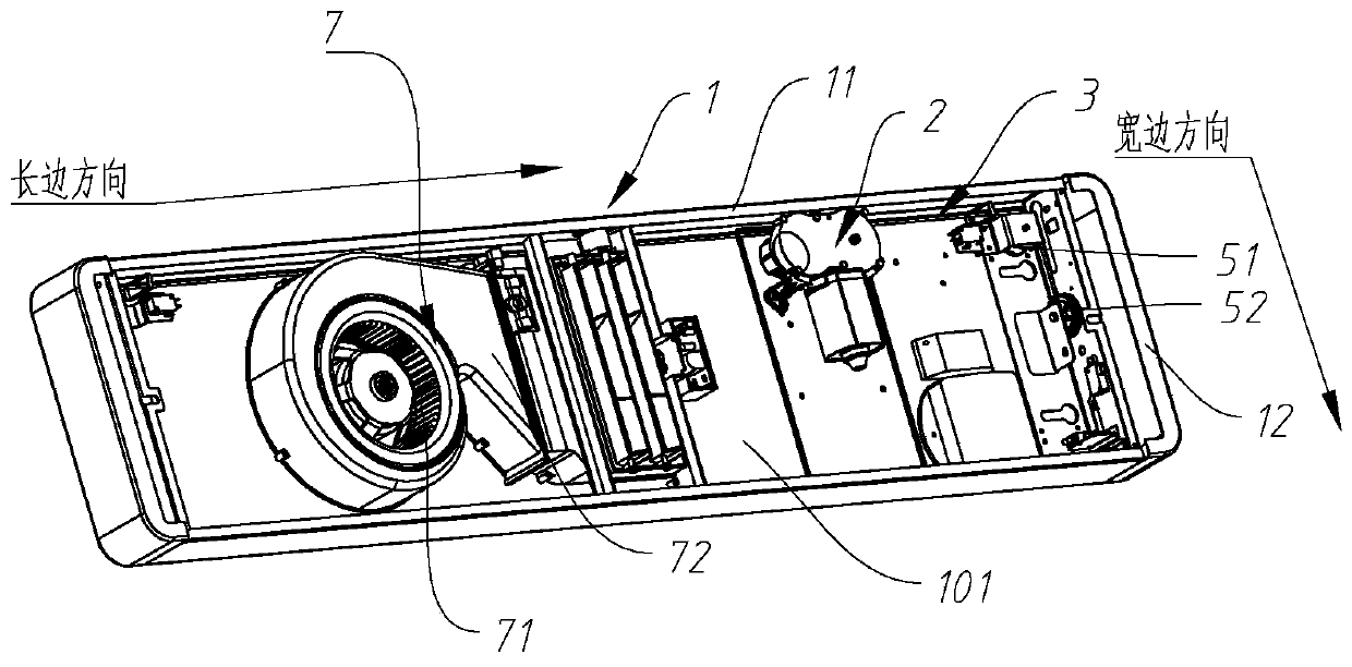
[0081] The pull wire 2 32 is wound out from the shaft of the winding machine 2 and folded to the side of the casing 1, and then the side of the adjacent casing 1 is reversed, and is extended along the long side of the casing 1, and then from the casing 1 The end of the switch is reversed and folded toward the outlet 2 132, and the wiring setting of the pull wire 2 32 is completed;

[0082] The winding-out position of the adjacent backguy wire 2 32 is provided with the reversing wheel 1 61 for making the backguy wire 2 32 fold toward the side of the casing 1, and the adjacent wire outlet 2 132 is set for making the backguy wire 2 32 fold toward the wire outlet 2 132 The reversing wheel two 62; the top of the outlet two 132 is provided with a reversing wheel three 63, which is simple in structure and easy to manufacture.

[0083] Such as Figure 9-10 As shown, a specific embodiment of the structure of the impeller 71 of the present invention: the extension direction of the rota...


PUM


Abstract

The invention discloses an electric clothes drying machine, and belongs to the technical field of clothes drying machines. Shells of the existing clothes drying machines are relatively high and cannotbe thin, the application range of the clothes drying machines is narrow, and popularization and sales are not facilitated. A winder is assembled on the side wall or the end wall of an adjacent machine shell, and the extending direction of a rotating shaft of the winder is perpendicular to the long edge of the machine shell, so that the winding direction of a pull rope is parallel to the long edgeof the machine shell. Due to continuous exploration, the existing technical prejudice that the pull rope has to be centrally arranged is broken, and a pull rope side end arranging structure is provided. The pull rope is arranged along the side end of the machine shell and adjacent to the side wall of the machine shell, can avoid a fan, an air duct and other parts, and fully utilizes the space ofthe machine shell. The pull rope, the fan and other parts are not in the same vertical surface, and the vertical height of the machine shell can be effectively reduced, so that the machine is compactin structure, popularization and sales can be facilitated, the reversing frequency of the pull rope can be effectively reduced, friction of the pull rope is reduced, the service life of the pull ropeis prolonged, and popularization and sales of the electric clothes drying machine are facilitated.

Description

technical field [0001] The invention relates to an electric clothes drying machine, which belongs to the technical field of clothes drying machines. Background technique [0002] Chinese patent (notification number CN 208072041 U) discloses an intelligent clothes drying machine, including a host, a drying rack and a drawstring: the drying rack is suspended below the host through the drawstring, and the drying rack can be Slide relative to the drawstring. The intelligent clothes drying machine of the present invention suspends the drying rack below the main machine through a drawstring, the drawstring is connected to both sides of the drying rack, and the drying rack is slidably connected to the drawstring. [0003] But above-mentioned scheme and existing drying machine, in order to be convenient to stay cord pull symmetrically arranged drying rack, stay cord is assembled in the middle position of clothes dryer, and the middle position of clothes dryer is equipped with blowe...

Claims


Application Information

Patent Timeline
Patent Type & Authority Applications(China)
IPC IPC(8): D06F58/00D06F58/20D06F57/12D06F53/04
CPCD06F53/045D06F57/125D06F58/00D06F58/20
Inventor 陈剑高守勇丁培森宋皖皖
Owner AUPU HOME STYLE CORP LTD
Why Eureka
Try Eureka