
Plugging and monitoring device for grouting material insteel bar grouting joint

A monitoring device and grouting material technology, which are applied in the direction of measuring device, lubrication indicating device, construction material processing, etc., can solve the problems of difficult joint sealing, reliable sealing of grouting material, environmental pollution on site of grouting material, and easy occurrence of grouting leakage, etc., so as to improve the connection strength. and connection quality, improve construction efficiency and work quality, and improve the effect of ergonomics

Pending Publication Date: 2019-11-26
CENT RES INST OF BUILDING & CONSTR CO LTD MCC GRP +1
View PDF0 Cites 1 Cited by
  • Summary
  • Abstract
  • Description
  • Claims
  • Application Information

AI Technical Summary

Problems solved by technology

[0005] In short, the existing technology of plugging the grouting joints with rubber plugs is difficult to ensure that each joint can be sealed reliably, prone to grout leakage, waste of materials, and the grouting material pollutes the site environment, and it is difficult to timely install the grouting material when the grouting material is fluid. It is found that the grouting material in the joint is not full, and the final appearance inspection of the grouting material in the hole is also very inconvenient. These problems have always plagued the grouting connection construction, affecting the construction efficiency and the connection quality of the structural steel grouting joint

Method used


Image

  • Plugging and monitoring device for grouting material insteel bar grouting joint
  • Plugging and monitoring device for grouting material insteel bar grouting joint
  • Plugging and monitoring device for grouting material insteel bar grouting joint

Examples


Embodiment Construction

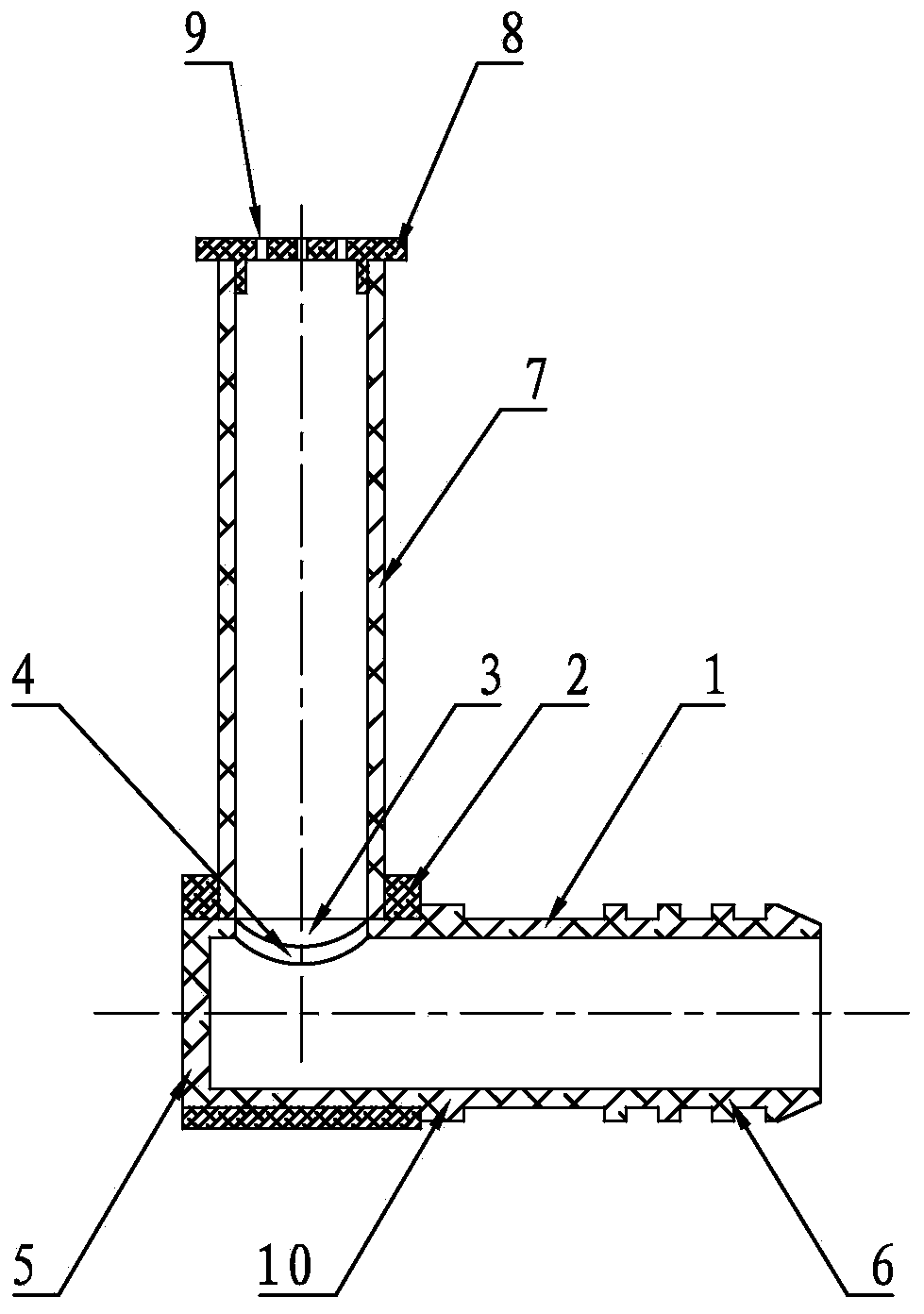
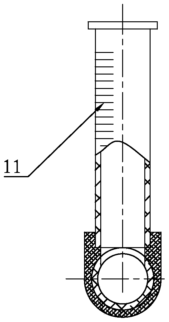
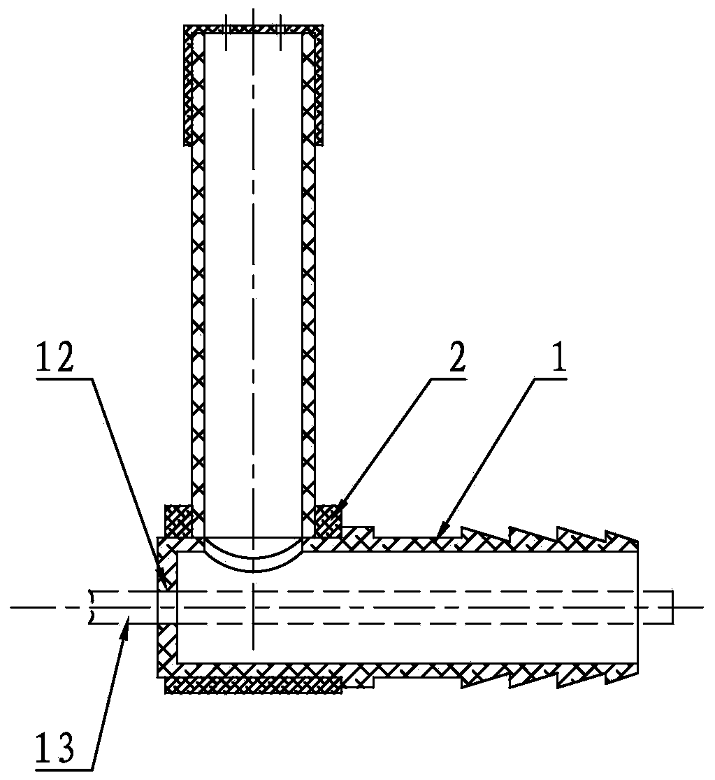
[0040] Some specific embodiments of the present invention will be described in detail below in an exemplary and non-limiting manner with reference to the accompanying drawings. The same reference numerals in the drawings designate the same or similar parts or parts. It should be understood by those skilled in the art that these drawings are not necessarily drawn to scale.

[0041] see Figure 1a and Figure 1b , the present invention provides a grouting plugging and monitoring device for steel grouting joints, comprising a plugging pipe 1, a closed ring 2, a monitoring pipe 7 and a venting cover 8, wherein the plugging pipe 1 is a pipe body with one end closed and the other open, The closed end of the plugging pipe 1 is provided with a transparent bottom surface 5, and the open end is connected to the grouting hole 19 of the steel bar grouting joint of the vertical prefabricated component, and the first grouting hole 4 is provided near the wall surface of the closed end of th...


PUM

PropertyMeasurementUnit
The inside diameter ofaaaaaaaaaa
Lengthaaaaaaaaaa
Diameteraaaaaaaaaa

Abstract

The invention provides plugging and monitoring device fora grouting materialin a steel bar grouting joint. The plugging and monitoring device comprises a plugging pipe, a sealing ring, a monitoring pipe and a ventilation cover,the sealing end of the plugging pipe is provided with a transparent bottom surface, the opening end is connected to a grout outlet hole of the steel bar grouting joint, andthe plugging pipe is provided with a first grout through hole; the sealing ring sleeve outside the plugging pipe, and the annular outer wall of the sealing ring is provided with a second grout throughhole;the monitoring pipe can be vertically inserted into the second through hole to form a detachable fixed connection; and the ventilation cover forms a detachable fixed connection with the upper end of the monitoring pipe, and at least one ventilation hole is formed in the ventilation cover. According to the plugging and monitoring device, installation is conducted before grouting, an operatorcan visually observe a position of a grouting material slurry surface in the monitoring pipe, slurry supplying can be conducted in time when grouting material slurry backflow occurs, construction difficulty is reduced, the grouting quality and construction efficiency are improved, the cost is low and waste of the grouting material can be avoided.

Description

technical field [0001] The invention relates to a grouting material plugging and monitoring device for steel bar grouting joints, belonging to the field of fabricated concrete buildings. Background technique [0002] In the prefabricated concrete structure, the installation and connection of vertical prefabricated components of concrete often use grouting joints to connect the vertical steel bars of the components. Common methods include: sleeve grouting connection, grout anchor lap connection, etc. At present, when these methods are applied to the grouting connection construction of vertically connected prefabricated components on site, the grouting holes and grouting holes of the grouting joints are mainly blocked by conical rubber plugs, and the friction between the plugging plugs and the hole wall is greater than that of the grout in the holes. The pressure of the material can ensure a reliable seal. If the friction between the rubber plug and the hole wall is insufficie...

Claims


Application Information

Patent Timeline
IPC IPC(8): E04G21/02E04C5/16G01F23/02
CPCE04C5/165E04G21/02G01F23/02
Inventor 谢松朱清华郝志强郝敏王爱军郭耀斌钱冠龙赵思远程亮方正
Owner CENT RES INST OF BUILDING & CONSTR CO LTD MCC GRP
Learn More