
Pressure-controllable layered grouting type sleeve valve tube and grouting method

A sleeve valve tube and grouting technology, which is applied in the field of controllable pressure layered grouting sleeve valve tube and grouting, can solve problems such as insufficient grouting pressure, adjustment of grouting pressure, high grouting pressure, etc., and achieve structural Simple, improved grouting quality, and convenient operation

Pending Publication Date: 2019-07-12
POWERCHINA RAILWAY CONSTR +2
View PDF0 Cites 8 Cited by
  • Summary
  • Abstract
  • Description
  • Claims
  • Application Information

AI Technical Summary

Problems solved by technology

Traditional sleeve valve grouting cannot accurately adjust the grouting pressure according to the properties of different formations, which may cause formation instability due to excessive grouting pressure, or insufficient reinforcement strength of the formation due to insufficient grouting pressure
At the same time, it is difficult to carry out accurate layered grouting, which eventually leads to unsatisfactory grouting effect

Method used


Image

  • Pressure-controllable layered grouting type sleeve valve tube and grouting method
  • Pressure-controllable layered grouting type sleeve valve tube and grouting method
  • Pressure-controllable layered grouting type sleeve valve tube and grouting method

Examples


Embodiment Construction

[0026] The present invention will be further described below in conjunction with the accompanying drawings and embodiments.

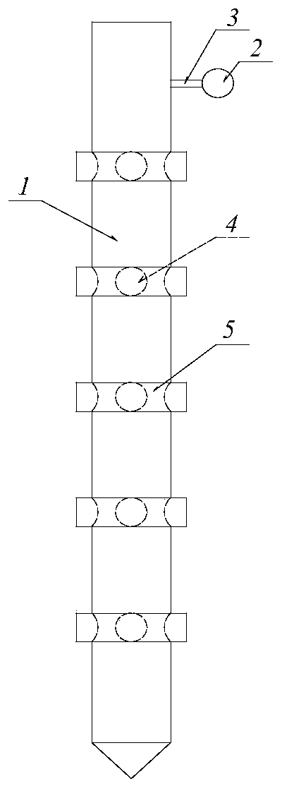
[0027] refer to figure 1 , a controllable pressure layered grouting sleeve valve tube of the present invention includes an outer tube 1, an inner tube 6, a rotating handle 15 and a pressure measuring device. refer to figure 2 , the lower end of the outer tube 1 is closed, the upper inner wall has an internal thread section, the lower tube wall is provided with multiple layers of outer tube slurry outlets at equal intervals in the longitudinal direction, and each layer of outer tube slurry outlets is composed of at least two circumferentially evenly distributed outlet holes. The slurry hole 4 is formed, and the rubber check valve 5 for sealing the slurry outlet holes of each layer of the outer tube is set on the outer wall of the outer tube 1. refer to image 3 , the lower end of the inner tube 6 is closed, and the lower tube wall is provided with mu...


PUM


Abstract

The invention discloses a pressure-controllable layered grouting type sleeve valve tube and a grouting method. Controllable pressure and accurate layered grouting are realized, and grouting quality iseffectively improved. The pressure-controllable layered grouting type sleeve valve tube comprises an outer tube, an inner tube, a rotating handle and a pressure measuring device, wherein the lower end of the outer tube is closed, and the upper-part inner wall is provided with an inner threaded segment; multiple layers of outer tube grout outlet holes are longitudinally and equidistantly formed inthe lower-part tube wall in a spaced mode, and each layer of the outer tube grout outlet holes is composed of at least two grout outlet holes uniformly distributed in the circular direction; and rubber one-way valves for covering all the outer tube grout outlet holes are arranged on the outer wall of the outer tube; the lower end of the inner tube is closed, and multiple layers of inner tube grouting holes are longitudinally and equidistantly formed in the lower-part tube wall of the inner tube in a spaced mode; the center distance of adjacent two layers of the inner tube grouting holes is equal to the center distance of adjacent two layers of the outer tube grout outlet holes, and each layer of outer tube grouting holes is composed of at least two grouting holes with corresponding to thegrout outlet holes in number and position; and a rotating handle communicating with the inner tube longitudinally is fixedly installed at the upper end of the inner tube and used for inserting the inner tube main body into the outer tube, and an outer threaded segment on the upper part of the rotation is connected with the inner threaded segment of the outer tube in a threaded mode. The pressuremeasuring device comprises a pressure sensor fixedly installed on the outer wall of the inner tube at the positions of the grouting holes.

Description

technical field [0001] The invention relates to geotechnical engineering construction, in particular to a pressure-controllable layered grouting sleeve valve pipe and a grouting method. Background technique [0002] With the continuous development and utilization of underground space, various types of underground projects are gradually emerging. During the construction process, it is inevitable to encounter situations such as piercing under and adjacent to pile foundations. For such problems, grouting is usually used to strengthen the ground, reduce the disturbance of the construction to the ground and surrounding buildings, and avoid accidents. [0003] Traditional grouting methods include jet grouting, sleeve valve pipe grouting, etc. Among them, sleeve valve pipe grouting is a grouting method pioneered by the French Soletanche Foundation Engineering Company in the 1950s, also known as Soletanche3- Law. The sleeve valve pipe grouting process is recognized as the most rel...

Claims


Application Information

Patent Timeline
IPC IPC(8): E02D3/12
CPCE02D3/12
Inventor 祝全兵房师涛王波宋立平谢强刘文喜杨军焦瑞锋曹明伟周建辉李霄聂华杨春灿张军伟张骁李翔
Owner POWERCHINA RAILWAY CONSTR
Learn More