Concrete vibration rod

A vibrating rod and concrete technology, which is applied in construction, building structure, and building material processing, etc., can solve the problems of small vibration force, easy to break the flexible shaft, inconvenient use, etc., and achieve the effect of energy reduction

Pending Publication Date: 2019-11-26
河南科耐新能源科技有限公司
View PDF0 Cites 0 Cited by
  • Summary
  • Abstract
  • Description
  • Claims
  • Application Information

AI Technical Summary

Problems solved by technology

[0004] Like this, just there is such shortcoming in the vibrating bar of prior art: motor and vibrating head are far apart, and the energy that motor produces is lost too much in the transmission process, and flexible shaft is easy to break, frequency is low, the shortcoming such as vibration force is little; The vibrating motor

Method used


Image

  • Concrete vibration rod
  • Concrete vibration rod

Examples


Embodiment Construction

[0022] The present invention will be further described below in conjunction with the accompanying drawings.

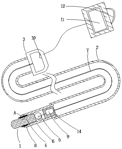
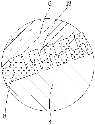
[0023] Such as figure 1 , 2 As shown, a concrete vibrating rod includes a vibrating rod body, the vibrating rod body has a head end 1, a middle section 2 and a tail end 3, the tail end is a hand-held end, and the head end is used When extending into one end in the concrete, the head end is equipped with a vibrating head 4, the middle section is a part connecting the head end and the tail end, the middle section is a rubber hose, and it is characterized in that: The head end has a hollow shell 6, the vibrating head is installed on the front end of the shell and extends out of the shell, and it also includes a vibrating motor 5 installed in the shell of the head end, the vibrating motor has vibrating power The output end of the vibration power of the vibration motor is directly connected to the vibration head, the vibration motor has a power cord 7, and the power cord ...


PUM


Abstract

The invention relates to the technical field of building equipment, in particular to a concrete vibration rod. The concrete vibration rod comprises a vibration rod body, the vibration rod body is provided with a first end, a middle segment and a tail end, the tail end is a hand-held end, the first end is the end extending into concrete during using, the first end is provided with a vibration head,the middle segment is a component connecting the first end with the tail end, the middle segment is a rubber hose, the first end is provided with a hollow shell, the vibration head is mounted at thefront end of the shell and extends out of the shell, the concrete vibration rod further comprises a vibration motor mounted in the shell of the first end, the vibration motor is provided with a vibration power output end, the vibration power output end of the vibration motor is directly connected with the vibration head, the vibration motor is provided with a power wire, and the power wire passesthrough the middle of the rubber hose. The concrete vibration rod has the advantage of less energy consumption.

Description

technical field [0001] The invention relates to the technical field of construction equipment, in particular to a concrete vibrating rod. Background technique [0002] The concrete vibrator is a device for tamping concrete and discharging air bubbles in the concrete. It includes a vibrator body. The vibrator body has a head end, a middle section and a tail end. The tail end is a hand-held end. The head end is the end protruding into the concrete during use, the head end is equipped with a vibration head, and the middle section is a part connecting the head end and the tail end. [0003] In the prior art, the motor is installed at the tail end, and the motor is connected with a flexible shaft, and the flexible shaft is connected with the vibrating head, and the motor transmits power to the vibrating head through rotation, and the vibrating head is also generated by internal swinging and knocking. The vibration can make the concrete vibrate to achieve the effect of vibration....

Claims


Application Information

Patent Timeline
IPC IPC(8): E04G21/08
CPCE04G21/08
Inventor 张丽其他发明人请求不公开姓名
Owner 河南科耐新能源科技有限公司
Why Eureka
Try Eureka