Integrated method for oil testing and well completion

A technology for oil testing and well completion pipe strings, which is applied in earthwork drilling, drilling equipment, wellbore/well components, etc. It can solve the problems of oil and gas production layers that cannot restore production capacity, increase engineering difficulty, and space constraints, etc., to achieve High efficiency of oil testing and layer transfer, reduced well control risks, and reduced production costs

Pending Publication Date: 2019-11-26
CHINA NAT PETROLEUM CORP CHUANQING DRILLING ENG CO LTD +1
View PDF12 Cites 1 Cited by
  • Summary
  • Abstract
  • Description
  • Claims
  • Application Information

AI Technical Summary

Problems solved by technology

[0003] There are many processes and long working hours, so it cannot be put into production in time
Oil testing generally includes more than ten steps such as drilling, wall scraping, running test strings, perforating, reservoir stimulation, blowout and fluid discharge, production testing, well killing, and testing strings. Including nearly ten steps such as secondary wellbore preparation, running the completion string, fluid replacement, setting, and blowout. Some wells even need secondary acidification to restore production capacity, which will take a lot of time
[0004] Multiple well kills will cause pollution to the oil and gas production layer, and even cause permanent damage in serious cases, making it impossible for the oil and gas production layer to restore its due production capacity
[0005] It is easy to cause problems such as pipe string stuck and buried, which increases the difficulty of the project. If it is handled carelessly, it may even cause the wellbore to be scrapped, resulting in a great waste of resources
The oil test string is equipped with test tools such as packers and test valves, and the space in the channel is limited. During the well killing process, plugging materials are easy to accumulate at the tools and bury the string, making it difficult to remove the test string.

Method used


Image

  • Integrated method for oil testing and well completion
  • Integrated method for oil testing and well completion
  • Integrated method for oil testing and well completion

Examples


Embodiment Construction

[0021] Hereinafter, an integrated method for well testing and completion of the present invention will be described in detail with reference to the accompanying drawings and exemplary embodiments.

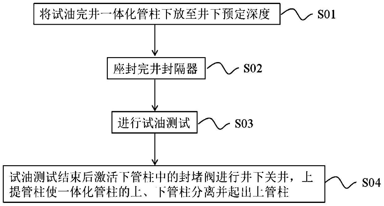
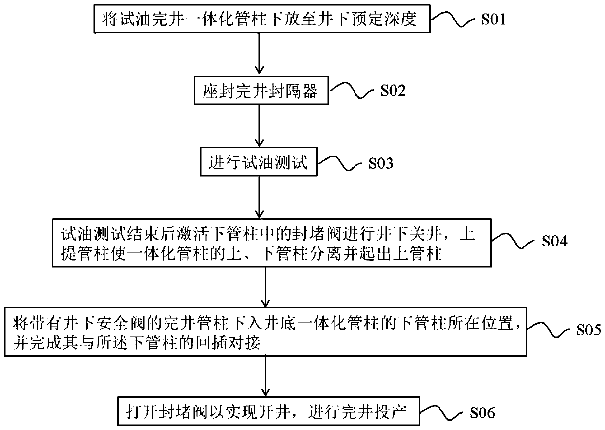
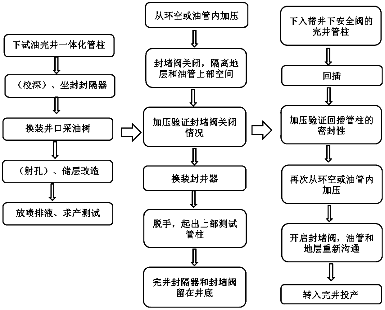
[0022] figure 1 A flow chart of a well testing and completion process according to an exemplary embodiment of the integrated method for well testing and well completion according to the present invention is shown. figure 2 It shows a flow chart of well testing and completion process according to another exemplary embodiment of the integrated method of well testing and completion according to the present invention. image 3 A schematic flow chart of a well testing and completion process is shown according to yet another exemplary embodiment of the integrated method for well testing and completion according to the present invention. Figure 4 A schematic diagram of step-by-step implementation of well testing and completion is shown according to yet another exemplary embodiment of t...


PUM


Abstract

The invention provides an integrated method for oil testing and well completion. The integrated method includes the steps that when an oil testing test is performed, an integrated pipe column composedof an upper pipe column and a lower pipe column which are detachably connected is lowered to a downhole predetermined depth, a packer in the integrated pipe column is subjected to setting, the oil testing test is performed, after the oil testing test is completed, a plugging valve is activated to perform shut-in downhole, and the upper pipe column and the lower pipe column are separated and the upper pipe column is lifted out; and when well completion and production are performed, a completion pipe column with a downhole safety valve is lowered into the bottom of a well and connected with thelower pipe column in a back inserting and abutting mode, the plugging valve is opened by pressure from an annulus or an oil pipe to realize well completion, and well completion and production are performed. The integrated method has the beneficial effects that the method has the advantages of saving operation procedures, being high in efficiency of well testing transfer, reducing engineering complexity, protecting oil and gas layers, reducing well control risks, reducing costs and the like.

Description

technical field [0001] The invention relates to the technical field of oil and gas well testing and completion equipment, in particular to an integrated method for oil testing and completion. Background technique [0002] At present, the oil testing and completion operations of most exploration wells or evaluation wells need to be completed in two steps. The first step is to lower the test pipe string with a series of tools such as test packer, test valve, and electronic pressure gauge to the vicinity of the production layer, and then conduct a blowout production test. plugging, this step is mainly for the purpose of obtaining formation data; if there is production, it is necessary to complete the well and put it into production, then go to the second step, and re-perform the wellbore preparation (including drilling plugs, wall scraping, well drilling, etc.), and then run into the belt to complete the well The completion strings of a series of tools such as packers and down...

Claims


Application Information

Patent Timeline
Patent Type & Authority Applications(China)
IPC IPC(8): E21B47/00E21B17/00
CPCE21B47/00E21B17/00
Inventor 贾海陈华良谢胜曾小军张明友潘登黄船庞东晓黄靖富周继东
Owner CHINA NAT PETROLEUM CORP CHUANQING DRILLING ENG CO LTD
Why Eureka
Try Eureka