Beam structure damage identification method based on support counterforce and deflection curvature

A technology for bearing reaction force and damage identification, which is used in machine/structural component testing, elasticity testing, measuring devices, etc., to solve problems such as the inability to identify the degree of structural damage and the need for pre-damage information.

Active Publication Date: 2019-11-26
XIANGTAN UNIV
View PDF9 Cites 8 Cited by
  • Summary
  • Abstract
  • Description
  • Claims
  • Application Information

AI Technical Summary

Problems solved by technology
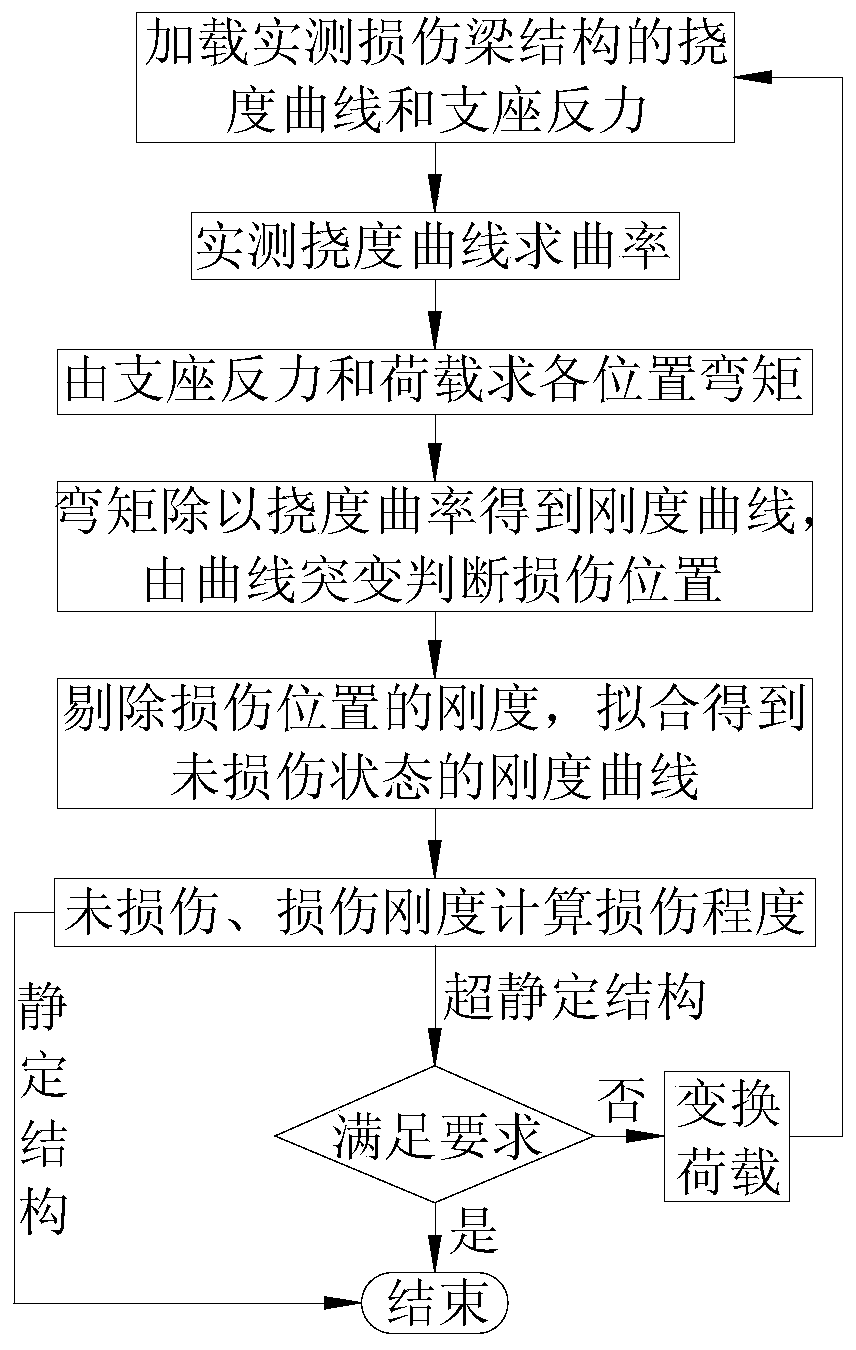
[0005] The purpose of the present invention is to provide a damage identification method for beam structures based on support reaction force and deflection curva

Method used


Image

  • Beam structure damage identification method based on support counterforce and deflection curvature
  • Beam structure damage identification method based on support counterforce and deflection curvature
  • Beam structure damage identification method based on support counterforce and deflection curvature

Examples


Embodiment 1

[0174] Embodiment one: see Figure 17 , the span of the simply supported beam is 100cm, and a unit is divided by 5cm, with a total of 20 units and 21 measuring points (the number in the upper circle in the figure is the unit number, and the lower number is the measuring point number). The cross-sectional size of the plate is b×h=4.5cm×1.5cm, and the elastic modulus of the material is 2.7×10 3 MPa, Poisson's ratio is 0.37, density is 1200kg / m 3 .

[0175] The damage in the actual engineering structure, such as the generation of cracks, material corrosion or the reduction of elastic modulus, generally only causes a large change in the structural stiffness, but has little impact on the quality of the structure. Therefore, in the finite element calculation, it is assumed that the damage of the structural element only causes the decrease of the stiffness of the element, and does not cause the change of the mass of the element. Damage to elements is simulated by a reduction in th...

Embodiment 2

[0184] Embodiment two: see Figure 22 , the span of the cantilever beam is 100cm, and a unit is divided by 5cm. There are 20 units and 21 measuring points in total (the numbers in the upper circle in the figure are unit numbers, and the numbers in the lower row are measuring point numbers). The cross-sectional size of the plate is b×h=4.5cm×1.5cm, and the elastic modulus of the material is 2.7×10 3 MPa, Poisson's ratio is 0.37, density is 1200kg / m 3 .

[0185] Considering that the fixed support end unit 1, the mid-span unit 10, and the free end unit 20 have different degrees of damage, the damage conditions are shown in Table 2.

[0186] Table 2 Multiple damage conditions of cantilever beam

[0187]

[0188] The specific implementation steps are as follows:

[0189] Step 1: Apply a concentrated load of 10N to the No. 21 measuring point at the cantilever end of the damaged cantilever beam to obtain the measured deflection curve of the cantilever beam after damage, and th...

Embodiment 3

[0195] Embodiment three: see Figure 27 , the span layout of the three-span continuous beam is 100+150+100cm, and 10cm is divided into one unit, a total of 35 units and 36 measuring points (the numbers in the upper circle in the figure are the unit numbers, and the lower numbers are the support numbers) . The cross-sectional size of the plate is b×h=4.5cm×1.5cm, and the elastic modulus of the material is 2.7×10 3 MPa, Poisson's ratio is 0.37, density is 1200kg / m 3 .

[0196] Unit 7 is located near the 0 point of the side span bending moment (ie, the inflection point of deflection curvature) under the action of a uniform load, unit 13 is located near the 0 point of the bending moment under the concentrated load of the mid-span, unit 18 is the mid-span unit of the middle span, and unit 26 is the third span The damage conditions of the maximum negative bending moment unit are shown in Table 3.

[0197] Table 3 Damage conditions of three-span continuous beams

[0198]

[0...


PUM

PropertyMeasurementUnit
Elastic modulusaaaaaaaaaa
Densityaaaaaaaaaa

Abstract

The invention discloses a beam structure damage identification method based on support counterforce and deflection curvature. The method mainly comprises the steps of applying load to a damaged back beam structure to obtain an actually measured deflection curve and support counterforce; solving the curvature of the actually measured deflection curve; calculating the bending moment value of each position of the beam structure through the support counterforce and the load; obtaining the stiffness of each position of the beam structure by dividing the bending moment value of the corresponding position by the deflection curvature, and identifying the damage position through the sudden change of the stiffness curve of the damage state; eliminating the stiffness of the damaged position, and fitting the residual stiffness curve to obtain a stiffness curve of an undamaged state; and calculating the damage degree according to the stiffness curves of the damaged state and the undamaged state toobtain the structural stiffness of the damaged position. If the beam structure is a statically indeterminate structure, loads are applied to different positions of the structure for multiple times, damage positions, damage degrees and stiffness results under the action of multiple loads are obtained, and damage judgment is comprehensively conducted. The method can accurately position and quantifythe damage of the beam structure, and is applied to damage evaluation of the beam structure.

Description

technical field [0001] The invention belongs to the technical field of structural health monitoring, and in particular relates to a beam structure damage identification method based on support reaction force and deflection curvature of beam structure non-destructive testing technology. Background technique [0002] As the core content of bridge health monitoring system, structural damage identification has many identification methods. The overall damage identification methods developed at home and abroad mainly include: structural damage identification methods based on dynamic response and static response. The dynamic response parameter index mainly judges the structural damage through the change of the structural mode (vibration frequency and mode shape). This method has high requirements on the number of measuring points, the measurement accuracy of the sensor, and the identification method of the modal parameters. Another type of method is the damage identification metho...

Claims


Application Information

Patent Timeline
IPC IPC(8): G01M5/00
CPCG01M5/0008G01M5/0033
Inventor 唐盛华刘宇翔张学兵秦付倩楚加庆罗承芳杨文轩
Owner XIANGTAN UNIV
Why Eureka
Try Eureka