Self-circulating evaporating cooling distribution transformer

A distribution transformer and evaporative cooling technology, applied in the field of transformers, can solve the problems of transformer insulation damage, reduce the efficiency of ground rod replacement, increase the labor intensity of staff, etc., to ensure normal operation, reduce manual operation intensity, and enhance sound absorption efficiency. Effect

Active Publication Date: 2019-11-26
江西亿晟电气有限责任公司
View PDF5 Cites 2 Cited by
  • Summary
  • Abstract
  • Description
  • Claims
  • Application Information

AI Technical Summary

Problems solved by technology

The transformer is often impacted by lightning, and the voltage generated by the impact causes oscillation in the coil, causing the coil to generate a high oscillating voltage that damages the insulation of the transformer and affects the normal operation of the transformer. Generally, grounding devices such as lightning rods and grounding rods are installed. To protect the transformer from lightning impact, the grounding rod needs to be replaced after a long period of use. The replacement of the grounding rod is generally done by digging out the grounding rod from the ground, removing the wire connected to the grounding rod, and replacing it with a new grounding rod. After connecting the wires and then burying them in the ground, the whole process is manually operated, which greatly increases the labor intensity of the staff and also reduces the replacement efficiency of the grounding rods

Method used


Image

  • Self-circulating evaporating cooling distribution transformer
  • Self-circulating evaporating cooling distribution transformer
  • Self-circulating evaporating cooling distribution transformer

Examples


Embodiment Construction

[0031] The following will clearly and completely describe the technical solutions in the embodiments of the present invention with reference to the drawings in the embodiments of the present invention.

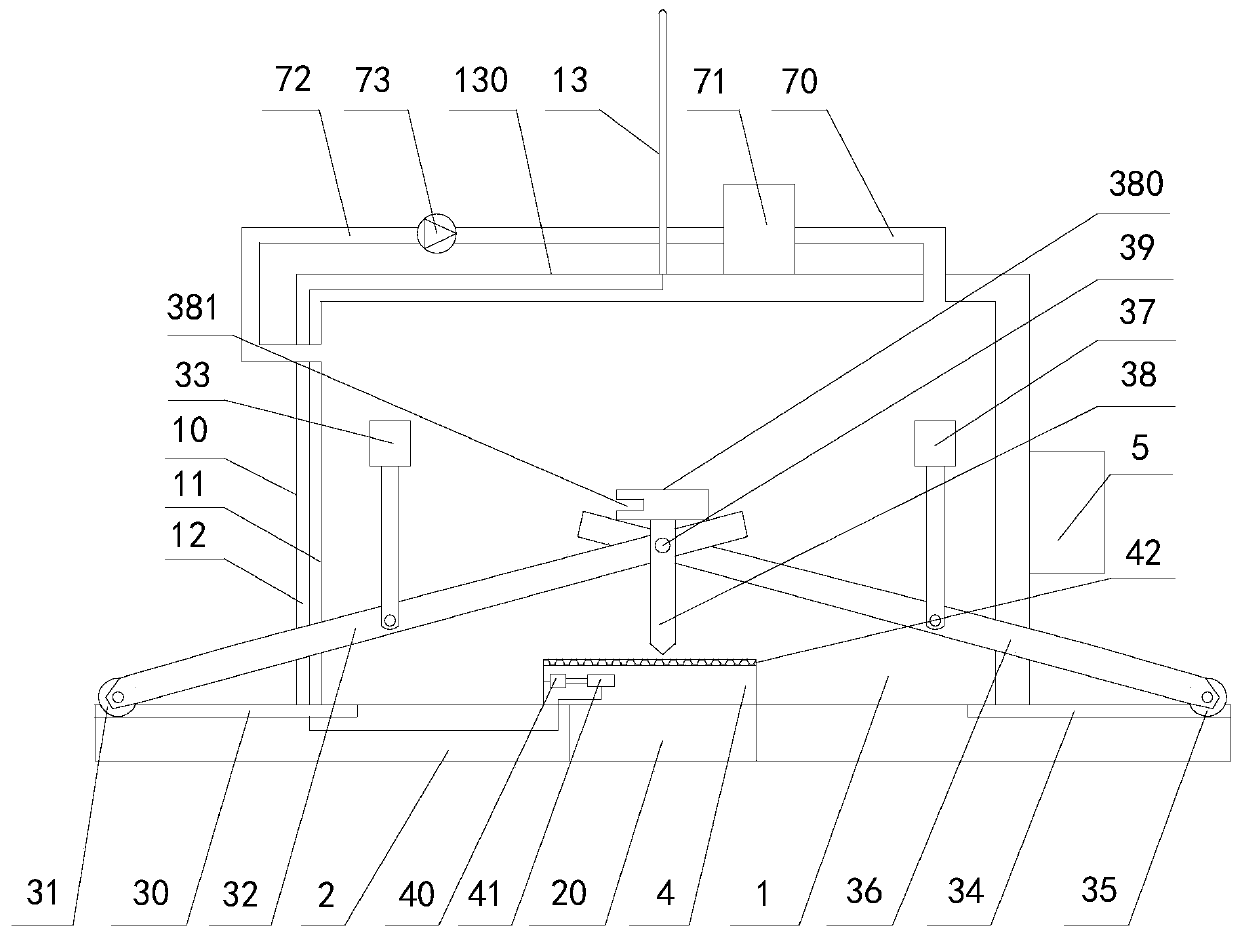
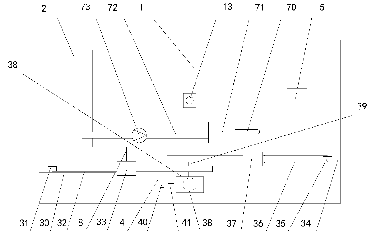
[0032] Such as Figure 1-3As shown, one embodiment of the present invention discloses a self-circulating evaporative cooling distribution transformer, including a transformer body 1, a base 2 located below the transformer body 1, and a ground rod lifting device. The transformer body 1 is fixed on the base 2, and the transformer body 1 is fixed on the base 2. The body 1 includes an outer shell 10 and an inner shell 11, and a sound-absorbing interlayer 12 is arranged between the outer shell 10 and the inner shell 11; a lightning rod 13 is arranged on the top of the transformer body 1, and the bottom of the lightning rod 13 is electrically connected to one end of a wire 130; the ground rod The lifting device is located directly in front of the transformer body 1. The grounding ro...


PUM


Abstract

The invention discloses a self-circulating evaporating cooling distribution transformer, relating to the technical field of transformers. The self-circulating evaporating cooling distribution transformer comprises a transformer body, a base and a grounded rod lifting device, wherein the transformer body is fixed on the base, the grounded rod lifting device comprises a first chute, a first contactroller, a first connection rod, a first electric push rod, a second chute, a second contact roller, a second connection rod, a second electric push rod and a grounded rod, a rotary shaft penetrates the upper end of the grounded rod, a round hole penetrates the middle of the base, and the upper part of the round hole is opposite to the lower end of the grounded rod. The two electric push rods are adopted as a power source so as to drive the middles of the two connection rods to move up and down, so that one end of each connection rod can move in the chute through the contact rollers, the otherend of each connection rod and the grounded rod that are coaxially connected move up and down as a whole, therefore, the grounded rod can insert into and pull out from ground automatically, manual operation intensity is relieved, and the grounded rod is replaced more efficiently.

Description

technical field [0001] The invention relates to the technical field of transformers, in particular to a self-circulating evaporative cooling power distribution transformer. Background technique [0002] The self-circulating evaporative cooling transformer uses the latent heat of vaporization when the cooling medium evaporates to take away the heat of the winding and iron core, and the heat taken away is condensed into liquid through the condenser and returned to the transformer oil tank. The transformer is often impacted by lightning, and the voltage generated by the impact causes oscillation in the coil, causing the coil to generate a high oscillating voltage that damages the insulation of the transformer and affects the normal operation of the transformer. Generally, grounding devices such as lightning rods and grounding rods are installed. To protect the transformer from lightning impact, the grounding rod needs to be replaced after a long period of use. The replacement o...

Claims


Application Information

Patent Timeline
Patent Type & Authority Applications(China)
IPC IPC(8): H01F27/00H01F27/34H01F27/18H01F27/33
CPCH01F27/00H01F27/18H01F27/33H01F27/345H01F2027/404
Inventor 彭昆蔡正平金水军李仁义李秋林
Owner 江西亿晟电气有限责任公司
Why Eureka
Try Eureka