
Ink application apparatus and method for applying ink

A coating device, ink technology, applied in chemical/electrolytic methods to remove conductive materials, printed circuit coatings, patterns and photolithography, etc., can solve problems such as difficult to speed up scanning

Inactive Publication Date: 2019-11-26
SUMITOMO HEAVY IND LTD
View PDF6 Cites 5 Cited by
  • Summary
  • Abstract
  • Description
  • Claims
  • Application Information

AI Technical Summary

Problems solved by technology

Therefore, it is difficult to speed up the scan

Method used


Image

  • Ink application apparatus and method for applying ink
  • Ink application apparatus and method for applying ink
  • Ink application apparatus and method for applying ink

Examples


Embodiment Construction

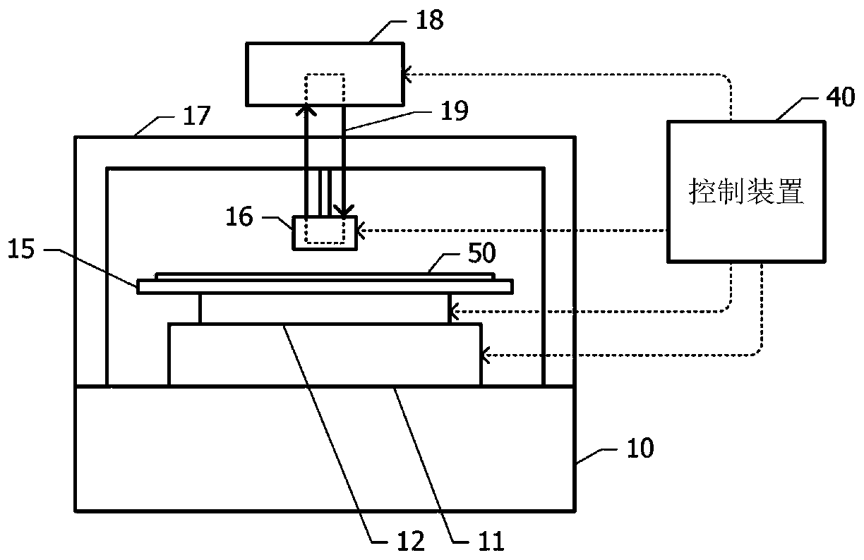
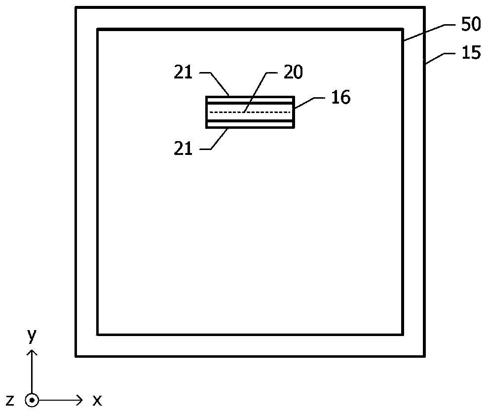
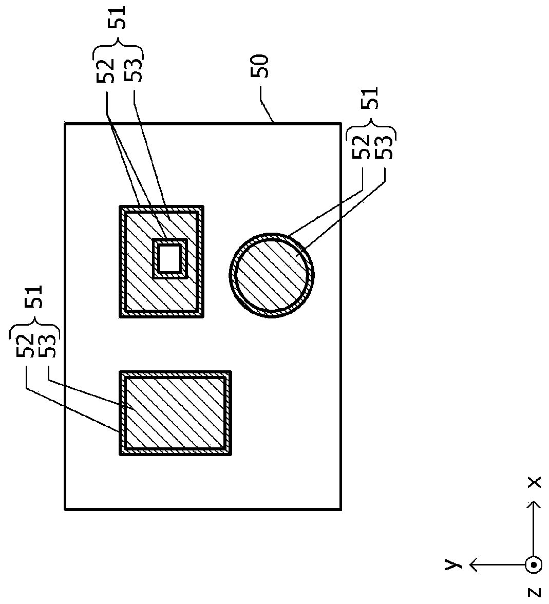
[0042] Below, refer to Figure 1A ~ Figure 3 , the ink application device based on the embodiment will be described.

[0043] Figure 1A It is a schematic diagram of the ink application apparatus based on an Example. On the stage 10 , a table 15 is supported via the XY stage 11 and the θ stage 12 . The object to be coated 50 is supported on the support surface of the table 15 . The object to be coated 50 is, for example, a substrate such as a printed circuit board. For example, the table 15 includes a vacuum chuck mechanism, and the object to be coated 50 is vacuum-adsorbed and fixed on the supporting surface. The supporting surface is, for example, parallel to the horizontal plane and faces upward in the vertical direction.

[0044]The XY stage 11 translates the table 15 relative to the stage 10 in two directions parallel to the supporting surface and perpendicular to each other. The θ stage 12 changes its posture in the rotation direction of the table 15 around the rota...


PUM


Abstract

The invention provides an ink application apparatus capable of shortening the processing time during ink coating. A moving mechanism moves one of the object to be coated and the inkjet head relative to the other so as to move a landing point of the ink with respect to the object to be coated on a surface of the object to be coated. A control device controls the inkjet head and the moving mechanism. One of the object to be coated and the inkjet head is moved relative to the other, and the ink is landed on an edge region along the edge of the region to be coated, thereby forming an edge portionmade of the ink in the edge region. In addition, after the edge portion is formed, one of the object to be coated and the inkjet head is moved relative to the other at a movement speed higher than a movement speed when the edge portion is formed, and the ink is applied to an inner region surrounded by the edge portion.

Description

[0001] This application claims priority based on Japanese Patent Application No. 2018-095507 filed on May 17, 2018. The entire contents of this Japanese application are incorporated herein by reference. technical field [0002] The invention relates to an ink coating device and an ink coating method. Background technique [0003] Ink coating technology using an inkjet head is attracting attention for forming a resist pattern of an etching mask when producing a printed board, forming a solder resist for a printed board, and the like. Patent Document 1 below discloses a method of dividing a region where a thin film is to be formed into a solid region and an edge region, and extracting pixels in the solid region to extract ink landing points. As a result, the distribution density of the impact points in the solid region becomes low, but the film in the solid region can be formed to a desired thickness by increasing the volume of the liquid droplets. [0004] Patent Document 1...

Claims


Application Information

Patent Timeline
Patent Type & Authority Applications(China)
IPC IPC(8): H05K3/06
CPCH05K3/061H05K2203/0548H05K3/0091H05K3/125H05K2203/013
Inventor 村野贤一
Owner SUMITOMO HEAVY IND LTD
Learn More