Automatic threading equipment and threading method applying same

An automatic threading and equipment technology, applied in the field of copper wire threading, can solve the problems of high labor intensity, cumbersome and complicated operation process, and achieve the effect of realizing automatic production, improving operation efficiency, and reliable and stable work

Active Publication Date: 2019-11-29
铜陵顶科线材有限公司
View PDF6 Cites 3 Cited by
  • Summary
  • Abstract
  • Description
  • Claims
  • Application Information

AI Technical Summary

Problems solved by technology

The finished copper wire with a specified diameter is obviously not able to meet the diameter requirement of the finished copper wire through one pass through the mold. It often needs to rely on multiple sets of wire drawing dies with gradually decreasing die hole diameters, and repeat the above operations more than ten times or even more than twenty times. Finished copper wire; in each drawing process, the copper wire is initially pulled out of the drawing die for a distance of about one meter, which must be completed by manual operation; especially for some thicker copper wires, the above The manual pulling operation is even more difficult, and sometimes several operators are required to complete it together
Obviously, the above-mentioned entire operation process is cumbersome and complicated, and the labor intensity is extremely high; while time-consuming and labor-intensive, the operation efficiency cannot be further improved, which seriously restricts the actual economic benefits of copper wire manufacturers.

Method used


Image

  • Automatic threading equipment and threading method applying same
  • Automatic threading equipment and threading method applying same
  • Automatic threading equipment and threading method applying same

Examples


Embodiment Construction

[0055] For ease of understanding, combined here Figure 1-5 , the concrete structure and working mode of the present invention are further described as follows:

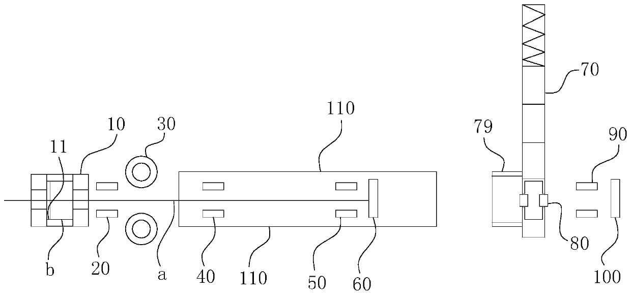
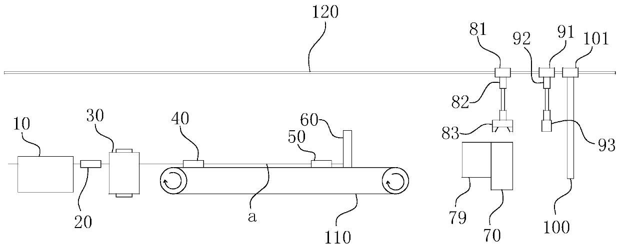
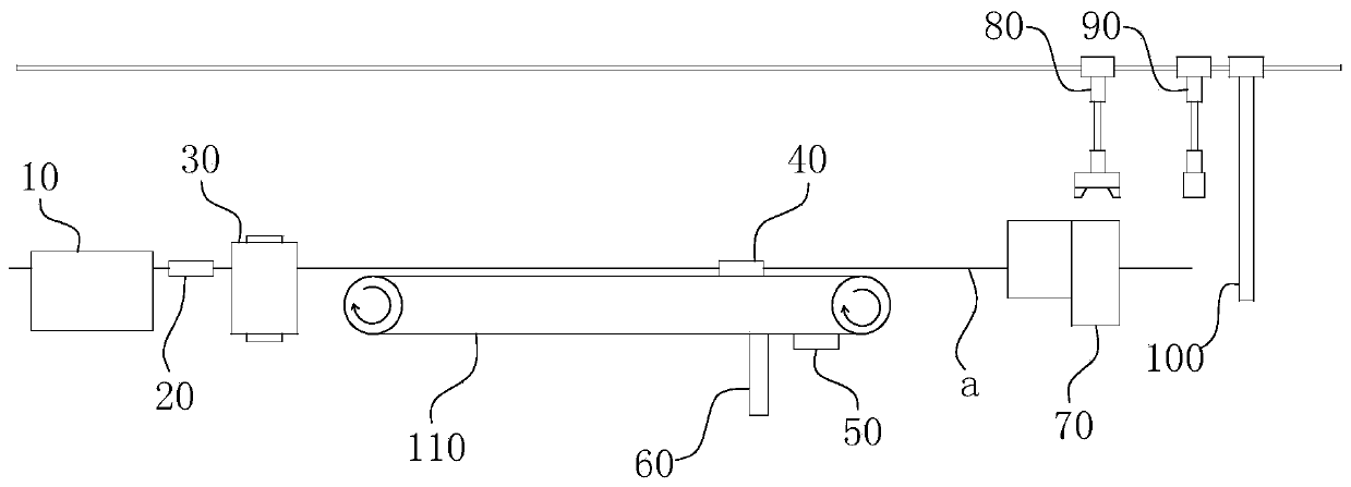
[0056] The specific embodiment structure of the present invention can refer to Figure 1-3 As shown, its main structure includes the first mold base 10, the first clamp 20, the clamping and conveying roller 30, the second clamp 40, the third clamp 50, and the first induction barrier 60 arranged in sequence along the direction of copper wire a. , the second mold base 70, the conveying fixture 80, the fourth fixture 90 and the second induction block 100, wherein:

[0057] Refer to the appearance of the first mold base 10 figure 1 The one shown is in the shape of a square, and the upper surface of the first mold base 10 is recessed with a receiving groove 11 where the axis of the cavity and the path of the copper wire coincide with each other. The shape of the receiving groove 11 is a three-stage necking groove with ...


PUM


Abstract

The invention belongs to the technical field of copper wire threading, in particular relates to automatic threading equipment and a threading method applying same. According to the automatic threadingequipment and a threading method applying the same can simply and quickly realize the automatic threading function of finished copper wires with specified diameters. The automatic threading equipmentcomprises a first die base, a first clamp, a clamping and conveying roller, a second clamp, a third clamp, a first induction baffle, a second die base, a conveying clamp, a fourth clamp and a secondinduction baffle which are sequentially arranged in the traveling direction of the copper wire. The threading method comprises the following steps that, the clamping and conveying roller feeds a copper wire; the first clamp and the third clamp break the copper wire to form a sharp point at the breakpoint of the copper wire; the second clamp clamps the copper wire and feeds the copper wire into thesecond die base; the fourth clamp draws the copper wire; the conveying clamp clamps a mold of the current process and feeds the mold into the first mold base, and meanwhile, the fourth clamp descendsand discharges the copper wire; and the conveying clamp and the fourth clamp are reset, and the second induction baffle is reset and the above steps are continuously repeated in sequence until all the molds in the second die base are used up.

Description

technical field [0001] The invention belongs to the technical field of copper wire threading, and in particular relates to an automatic threading device and a threading method using the device. Background technique [0002] At present, copper wire production generally adopts Ф5.5mm, Ф6.5mm, Ф8.0mm, etc. cold-rolled wire rods to undergo multiple drawing, intermediate heat treatment, surface treatment and other processes to obtain copper wires with required wire diameters, and then Then a plurality of copper wires are twisted into a wire and subjected to subsequent processing to finally obtain a finished wire. During the drawing process, no matter dry drawing or wet drawing, the copper wire needs to be processed and deformed through the die hole of the wire drawing die, and finally the finished copper wire with the required diameter is formed. Usually, for the drawing of copper wire, the operator needs to manually sharpen the copper wire head on the grinding wheel, and then i...

Claims


Application Information

Patent Timeline
Patent Type & Authority Applications(China)
IPC IPC(8): B21C5/00
CPCB21C5/006
Inventor 陈鼎彪陈彬陈城曹永成黄亮汪洋孙玉好胡伯顺吴晓山张槐林吴智云黄爱军李齐靖秦磊王帮助查敏王建华
Owner 铜陵顶科线材有限公司
Why Eureka
Try Eureka