Production process and production equipment of motor rotor for unmanned aerial vehicle

A technology of production equipment and production process, which is applied in the production process of motor rotors for drones and its production equipment, can solve the problems of poor motor performance, low degree of automation, and low production efficiency, so as to prevent wear and eccentricity, improve Production efficiency and degree of automation, the effect of high production efficiency

Active Publication Date: 2020-08-18
衢州市迈德电子有限公司
View PDF8 Cites 0 Cited by
  • Summary
  • Abstract
  • Description
  • Claims
  • Application Information

AI Technical Summary

Problems solved by technology

[0004] Electromagnetic DC motors are widely used on drones; electromagnetic DC motors are composed of stator poles, rotors (armatures), commutators (commonly known as commutators), brushes, casings, bearings, etc.; the rotor at this stage is for To avoid the axial current generated by electromagnetic induction, a layer or even multiple layers of insulating paint will be coated on the outer surface of the motor shaft to prevent the generation of axial current during use and cause the motor to burn out; and the rotor at this stage The conventional production process is to manually stamp the motor shaft and rotor shaft directly through the traditional concave die. This method has low production efficiency, low degree of automation, and is prone to tilting, which will cause the insulating paint on the outer wall of the motor shaft to wear and damage the motor. performance is adversely affected

Method used


Image

  • Production process and production equipment of motor rotor for unmanned aerial vehicle
  • Production process and production equipment of motor rotor for unmanned aerial vehicle
  • Production process and production equipment of motor rotor for unmanned aerial vehicle

Examples


Embodiment 1

[0047] A production process of a motor rotor for drones includes the following steps:

[0048] S1: Turn the rotor shaft blank into shape, and heat it through an electric melting furnace; and paint the surface for use;

[0049] S2: Punching the rotor pieces into a rotor piece group for use;

[0050] S3: The rotor sheet group and the rotor shaft are punched and formed by the cooperation of a punching machine and a punching die;

[0051] S4: Test the straightness of the rotor shaft of the rotor and leave the factory without error.

[0052] In the specific embodiment of the present invention, in step S3, the rotor shaft is immersed in oil before the rotary shaft sheet group and the rotor shaft are stamped.

[0053] Compared with the prior art, the method disclosed in the present invention has the following beneficial effects: the production process is simple to operate, has lower technical requirements for staff, and is suitable for more work groups; the production efficiency is high, and th...

Embodiment 2

[0055] Such as Figure 1-4 As shown, in addition, the present invention also discloses a production equipment of a motor rotor for unmanned aerial vehicles, which in turn includes a turning device, a resistance furnace, a stamping device, and a straightness testing device according to the production process; the turning device is a CJK6130 CNC lathe ; The resistance furnace is a ZXRJ-2-75 well type resistance furnace.

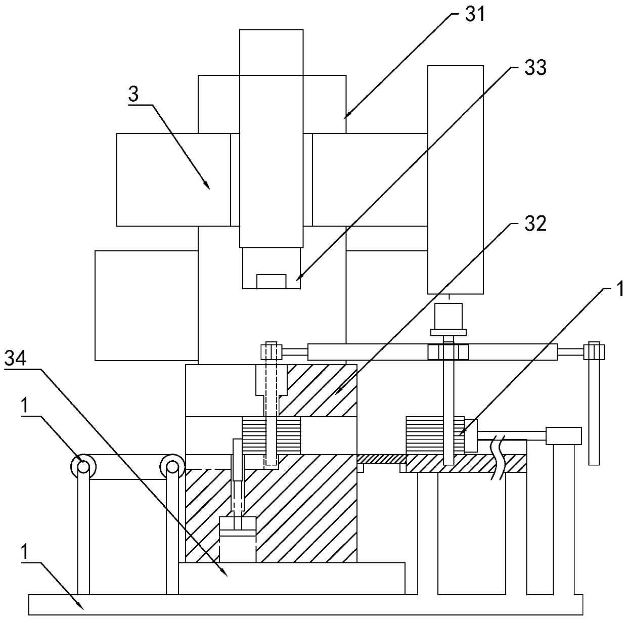
[0056] In a specific embodiment of the present invention, the punching device includes a frame 1, a PLC control unit, a feeding unit 2, a punching unit 3, and a discharging unit 4;

[0057] The PLC control unit, the punching unit 3, the feeding unit 2 and the discharging unit 4 are all installed on the frame 1; the punching unit 3, the feeding unit 2, and the discharging unit 4 are all electrically connected to the PLC system; the discharging unit 4 is the conveyor belt.

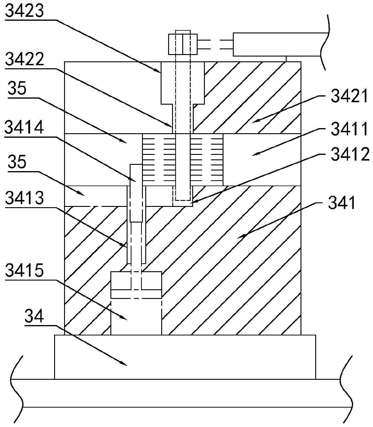
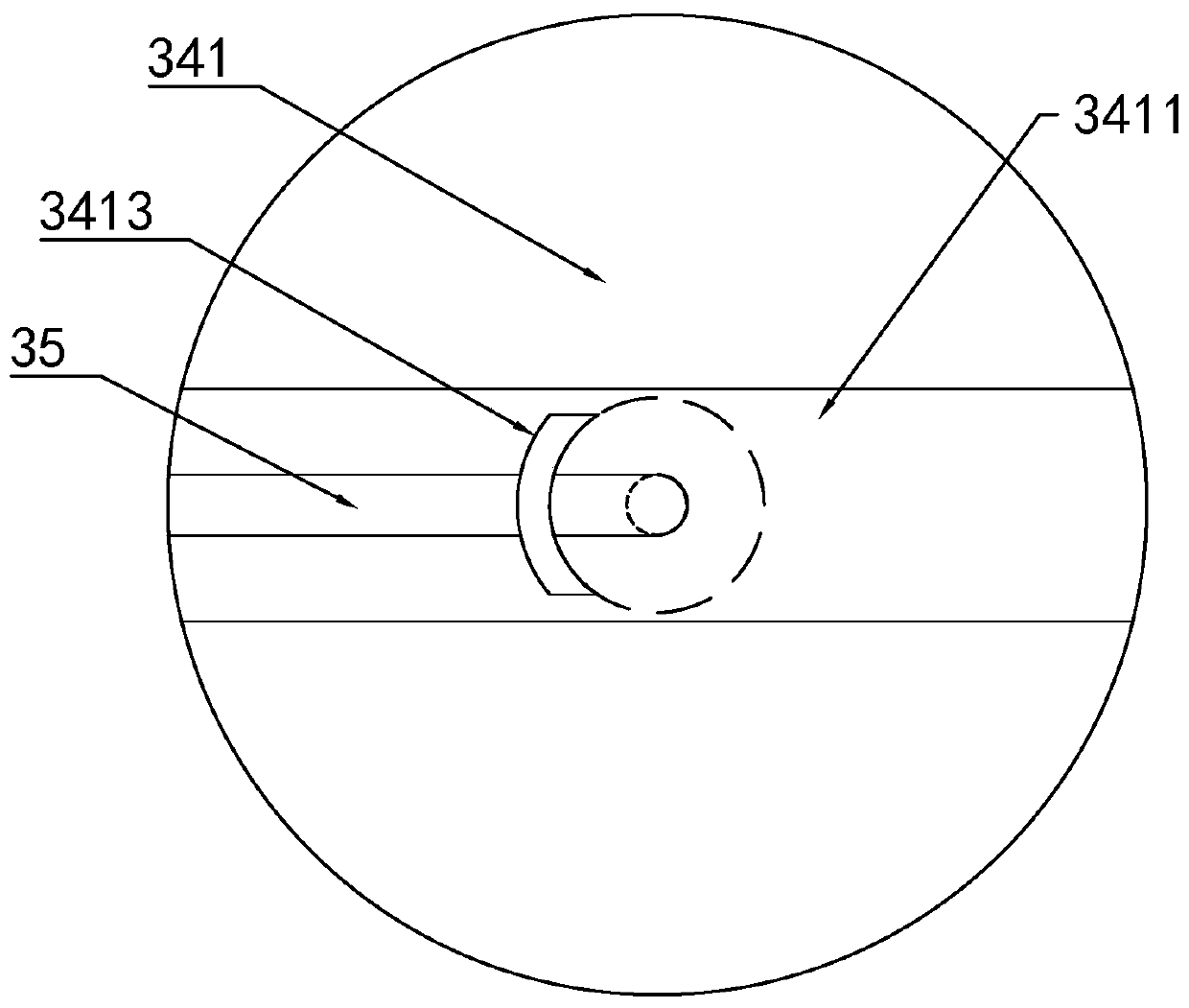
[0058] In the specific embodiment of the present invention, the punching unit 3 includes a punc...

Embodiment 3

[0064] Example 3, the difference from Example 2 is

[0065] Such as Figure 5-6 As shown, in the specific embodiment of the present invention, the feeding unit 2 includes a rotor sheet group feeding module 21 and a rotating shaft feeding module 22;

[0066] In a specific embodiment of the present invention, the rotor blade group feeding module 21 includes a feeding platform 211, a transverse drive cylinder 212, and a pushing plate 213 for pushing the rotor blade group; the feeding platform 211 is installed on the frame 1, two A feeding baffle 214 is installed on the side to form a feeding channel in the middle; the lateral drive cylinder 212 is installed on the frame, and the output end passes through the feeding channel toward the punching die 32; the push plate 213 is installed on the output of the lateral drive cylinder 212 And the pushing surface of the pushing plate 213 is set to a curved surface that fits the rotor sheet; the pushing plate 213 is installed with a displacement...


PUM


Abstract

According to the technical scheme, the production process of the motor rotor for the unmanned aerial vehicle comprises the following steps of: turning and forming a rotor shaft blank, and performing heat treatment through an electric melting furnace; painting the surface for later use; punching the rotor sheets into a rotor sheet group for later use; punching and forming the rotor sheet group andthe rotor shaft through the cooperation of a punching machine and a punching die; and testing the straightness of the rotor shaft of the rotor without leaving a factory. Compared with the prior art, the method disclosed by the invention has the beneficial effects that the production process is simple to operate, has lower technical requirements on workers, and is suitable for more working groups;the production efficiency is high, the quality of the produced motor rotor is good, the rotor shaft is subjected to oil immersion treatment, and after the rotor shaft for punching is lubricated by oil, an insulating paint layer on the surface is not easy to wear, so that the problem of electric leakage of the finished motor rotating shaft is avoided.

Description

Technical field [0001] The invention relates to the technical field of motor manufacturing, in particular to a production process and production equipment of a motor rotor for drones. Background technique [0002] Electric machinery (English: Electric machinery, commonly known as "motor") refers to an electromagnetic device that converts or transmits electrical energy according to the law of electromagnetic induction. [0003] The motor is represented by the letter M in the circuit (the old standard is D). Its main function is to generate driving torque. As the power source for electrical appliances or various machinery, the generator is represented by the letter G in the circuit. Its main function is The role is to convert mechanical energy into electrical energy. [0004] Electromagnetic DC motors are widely used in drones; electromagnetic DC motors are composed of stator poles, rotor (armature), commutator (commonly known as commutator), brushes, casing, bearings, etc.; the rotor...

Claims


Application Information

Patent Timeline
Patent Type & Authority Applications(China)
IPC IPC(8): H02K15/02H02K15/12
CPCH02K15/02H02K15/12
Inventor 杜江赵传步卢怡成张亮
Owner 衢州市迈德电子有限公司
Why Eureka
Try Eureka