A production process and production equipment of a motor rotor for unmanned aerial vehicles
A production process and motor technology, applied in the production process and production equipment field of motor rotors for drones, can solve the problems of low automation, low production efficiency, poor motor performance, etc., achieve good rotor quality and improve production The effect of efficiency and degree of automation
- Summary
- Abstract
- Description
- Claims
- Application Information
AI Technical Summary
Problems solved by technology
Method used
Image
Examples
Embodiment 1
[0047] A production process for a motor rotor for an unmanned aerial vehicle, comprising the steps of:
[0048] S1: Turning the rotor shaft blank into shape, and heat treatment in an electric melting furnace; and paint the surface for later use;
[0049] S2: Stamping the rotor sheet into a rotor sheet group for use;
[0050] S3: Stamping the rotor sheet group and the rotor shaft through the cooperation of the punching machine and the punching die;
[0051] S4: Test the straightness of the rotor shaft of the rotor, and leave the factory without error.
[0052] In a specific embodiment of the present invention, step S3 is to perform oil immersion treatment on the rotor shaft before stamping the rotor shaft sheet group and the rotor shaft.
[0053] Compared with the prior art, the beneficial effects brought by the method disclosed in the present invention are: the production process is simple to operate, has lower technical requirements for staff, and is suitable for more worki...
Embodiment 2
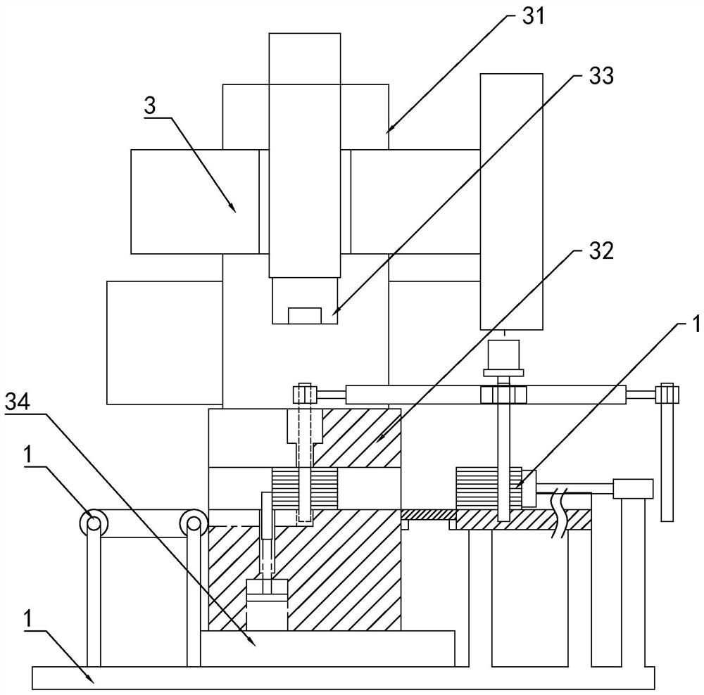
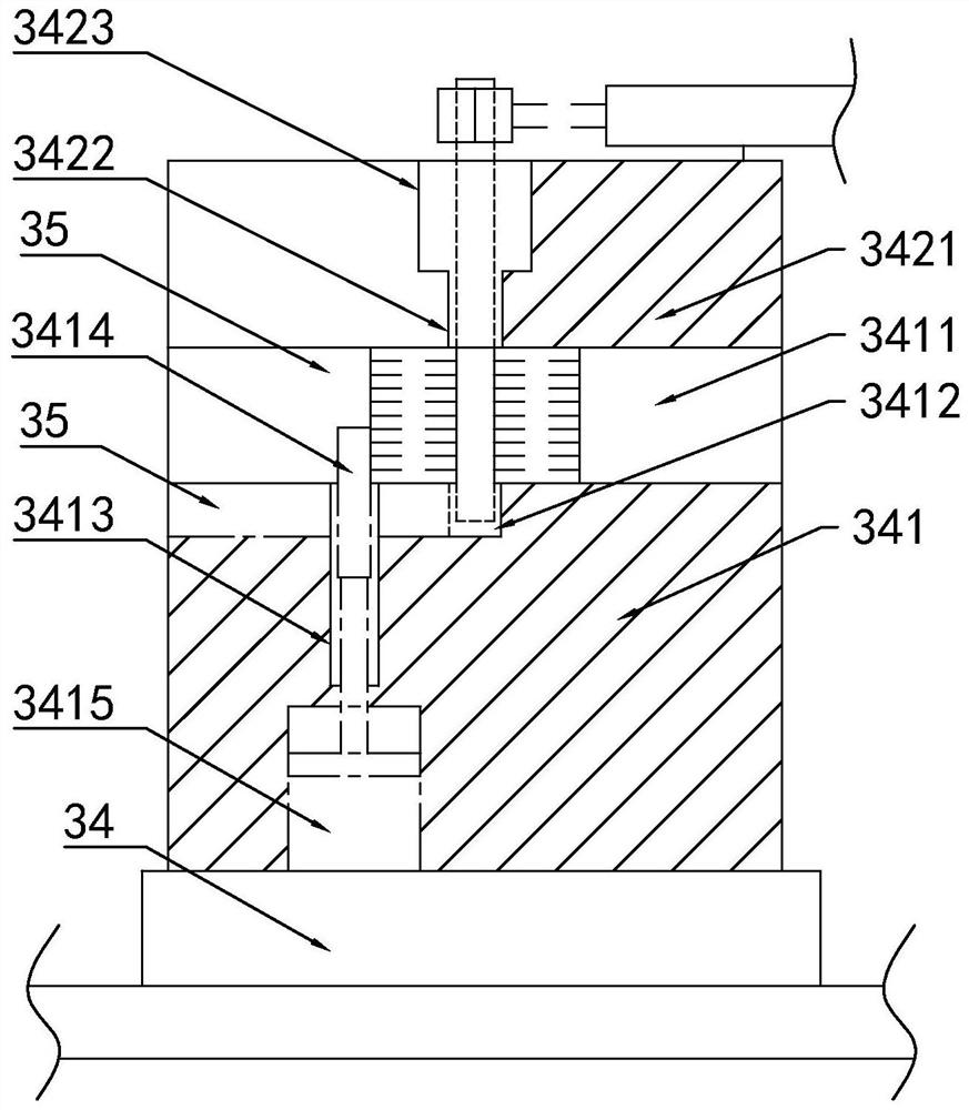
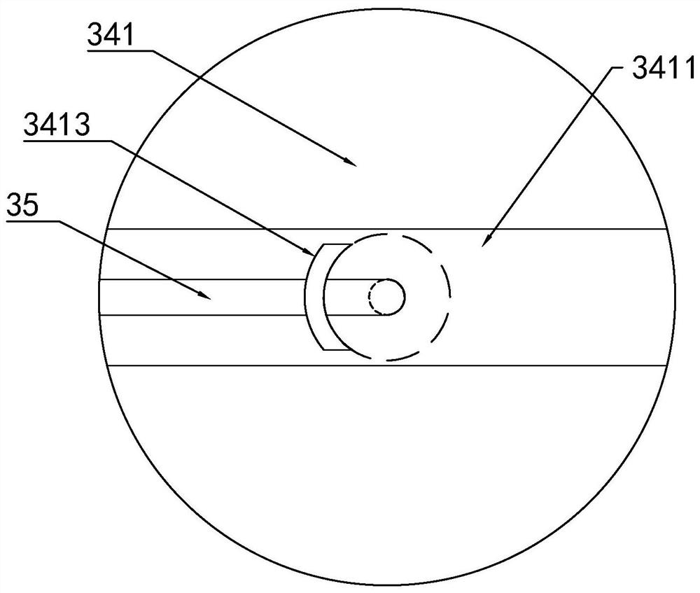
[0055] Such as Figure 1-4 As shown, in addition, the present invention also discloses a production equipment for motor rotors for unmanned aerial vehicles, which sequentially includes a turning device, a resistance furnace, a stamping device and a straightness testing device according to the production process; the turning device is a CJK6130 CNC lathe ; The resistance furnace is a ZXRJ-2-75 well-type resistance furnace.
[0056] In a specific embodiment of the present invention, the punching device includes a frame 1, a PLC control unit, a feeding unit 2, a punching unit 3, and a discharging unit 4;
[0057] Described PLC control unit, stamping unit 3, feeding unit 2 and discharging unit 4 are all installed on the frame 1; Stamping unit 3, feeding unit 2, discharging unit 4 are all electrically connected with PLC system; Described discharging unit 4 is the conveyor belt.
[0058] In a specific embodiment of the present invention, the punching unit 3 includes a punching mac...
Embodiment 3
[0064] Embodiment 3, differs from Embodiment 2 in that
[0065] Such as Figure 5-6 As shown, in a specific embodiment of the present invention, the feeding unit 2 includes a rotor sheet group feeding module 21 and a shaft feeding module 22;
[0066] In a specific embodiment of the present invention, the rotor sheet group feeding module 21 includes a feeding platform 211, a horizontal drive cylinder 212, and a push plate 213 for pushing the rotor sheet group; the feeding platform 211 is installed on the frame 1, and the two Side feed baffle plate 214 is installed, and feed channel is formed in the middle; Described lateral drive cylinder 212 is installed on the frame, and output end passes feed channel towards stamping mold 32; end; and the pushing surface of the pushing plate 213 is set as an arc surface adapted to the rotor sheet; the pushing plate 213 is equipped with a displacement sensor electrically connected to the plc system.
[0067] It should be noted that the roto...
PUM
 Abstract
Description
Claims
Application Information
 - R&D
- Intellectual Property
- Life Sciences
- Materials
- Tech Scout
- Unparalleled Data Quality
- Higher Quality Content
- 60% Fewer Hallucinations
Browse by: Latest US Patents, China's latest patents, Technical Efficacy Thesaurus, Application Domain, Technology Topic, Popular Technical Reports.
© 2025 PatSnap. All rights reserved.Legal|Privacy policy|Modern Slavery Act Transparency Statement|Sitemap|About US| Contact US: help@patsnap.com


