
A safe and reliable steel bar straightening machine for building construction

A technology of building construction and straightening machine, applied in the field of construction production equipment, can solve the problems of impacting operators, safety accidents, increasing the resistance of steel bar conveying steel bar by a steel bar straightening machine, etc., so as to reduce the force and strengthen the safety and reliability. Effect

Active Publication Date: 2020-12-04
四川省佳宇建设集团有限公司
View PDF5 Cites 0 Cited by
  • Summary
  • Abstract
  • Description
  • Claims
  • Application Information

AI Technical Summary

Problems solved by technology

[0003] In the actual building construction process, when using the steel bar straightening machine to straighten the steel bar, usually the coiled steel bar is placed directly on the ground, and the steel bar usually enters the steel bar straightening machine in a rotating manner, so during the straightening process, the steel bar The coil cannot follow the steel bar to keep a synchronous rotation state, which makes the steel bar conveyance difficult, which not only increases the resistance of the steel bar straightening machine to convey the steel bar, but also causes various safety accidents. Not only that, the steel bar straightening machine is straightening After the steel bar is cut, the steel bar cutting part is relatively sharp, and it is easy to jump out of the tray guide groove, hit the surrounding operators, cause a safety accident, and cause a significant reduction in the safety performance of the existing steel bar straightening machine

Method used


Image

  • A safe and reliable steel bar straightening machine for building construction
  • A safe and reliable steel bar straightening machine for building construction
  • A safe and reliable steel bar straightening machine for building construction

Examples


Embodiment Construction

[0024] The present invention will now be described in further detail with reference to the accompanying drawings. These drawings are all simplified schematic diagrams, and only illustrate the basic structure of the present invention in a schematic manner, so they only show the structures related to the present invention.

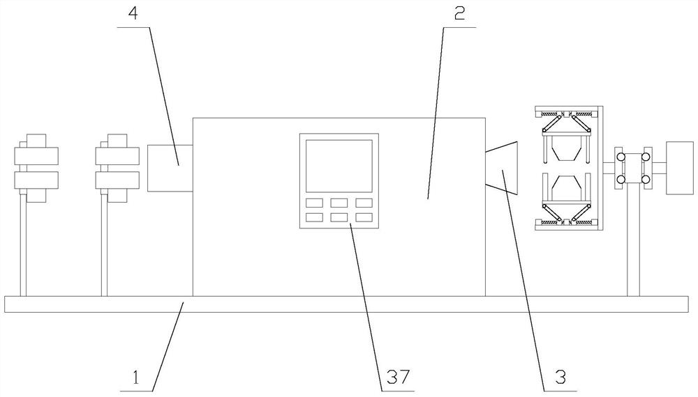
[0025] like figure 1 As shown, a safe and reliable steel bar straightening machine for building construction includes a base 1, a main engine 2, a feeding pipe 3, a discharging pipe 4, an operation panel 37, a placement mechanism and two supporting mechanisms. The material pipe 3 and the discharge pipe 4 are respectively fixed on both ends of the main machine 2, the operation panel 37 is fixed on the main machine 2, the operation panel 37 is provided with a display screen and several buttons, and the main machine 2 is provided with a PLC , the placement mechanism is located at the end of the feed pipe 3 away from the host 2, the support mechanism is located...


PUM


Abstract

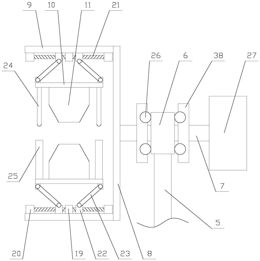
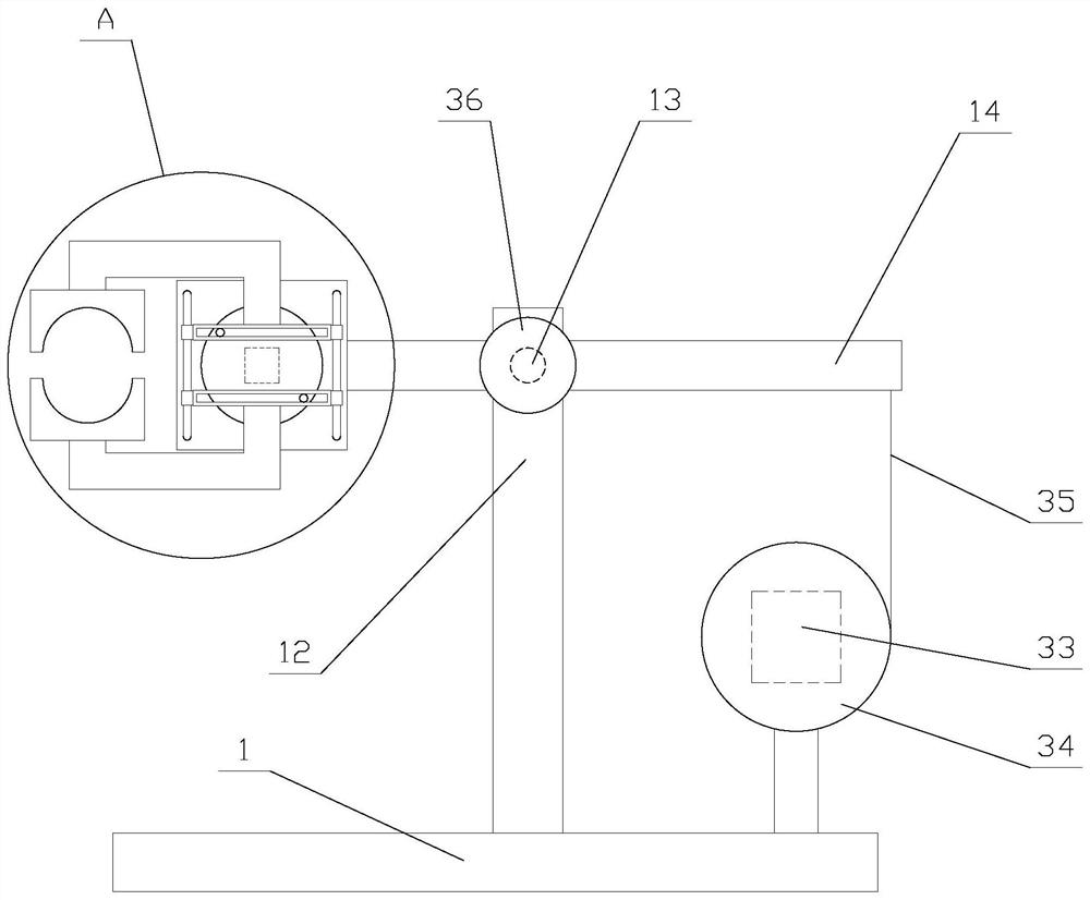
The invention relates to a safe and reliable steel bar straightening machine for building construction, and the steel bar straightening machine comprises a base, a host machine, a feeding pipe, a discharging pipe, an operating panel, a placing mechanism and two supporting mechanisms, wherein the placing mechanism comprises a supporting column, a sleeve ring, a rotating shaft, a flat plate and twoplacing assemblies, each placing assembly comprises a fixed plate, a telescopic unit, a telescopic disc and a placing block, and each supporting mechanism comprises a vertical plate, a fixed shaft, arotating plate, a rotating assembly, a connecting plate and a clamping assembly. The safe and reliable steel bar straightening machine for building construction is convenient to support and place steel bar discs through the placing mechanism, enables the steel bar discs to rotate synchronously along with the rotation of the steel bars in the host machine, reduces the acting force of the host machine for drawing the steel bars, limits the positions of the steel bar discs, ensures safe processing, and utilizes the two supporting mechanisms to fixedly clamp the cut steel bars, the steel bars areprevented from jumping out and smashing operators, and the safety and reliability of the device are further enhanced.

Description

technical field [0001] The invention relates to the field of construction production equipment, in particular to a safe and reliable steel bar straightening machine for construction. Background technique [0002] In modern construction projects, a large amount of steel bars and stirrups obtained by processing steel bars are required when making piling, beam-column reinforcing bars, and steel bars are usually stored and transported in the form of coils. Usually, steel bar straightening machines are used in construction projects to After the steel bars are straightened, they are cut to length and then used in general production. [0003] In the actual construction process, when using the steel bar straightening machine to straighten the steel bar, the steel bar coil is usually placed directly on the ground, and the steel bar usually enters the steel bar straightening machine in a rotating way. The coil cannot follow the synchronous rotation of the steel bar, which makes the s...

Claims


Application Information

Patent Timeline
Patent Type & Authority Patents(China)
IPC IPC(8): B21F1/02
CPCB21F1/026
Inventor 李志聪
Owner 四川省佳宇建设集团有限公司
Learn More