Robot intelligent oiling equipment

A technology of robots and equipment, applied in the directions of manipulators, packaging, liquid distribution, conveying or transfer devices, etc., can solve problems such as the inability to meet the refueling needs of large-flow refueling vehicles, irregular leakage of mechanical arms, and increased cost of gas stations. Achieve the effect of automatic operation, space saving and flexible fueling method

Active Publication Date: 2019-11-29
河南英高能源科技有限公司
View PDF8 Cites 0 Cited by
  • Summary
  • Abstract
  • Description
  • Claims
  • Application Information

AI Technical Summary

Problems solved by technology

At present, refueling mostly adopts the method of manual refueling. Although many gas stations have implemented self-service refueling, most gas stations are still equipped with operators to assist in refueling. Carry out refueling operations
When there are many refueling vehicles, it is difficult for fewer staff to take care of each refueling vehicle in an all-round way. If there are too many staff at the gas station, there will be a waste of human resources, and the efficiency of manual operation is relatively low. It is also low, and there will be work and operation errors, leading to safety accidents.
In addition to payment operations, fuel volume selection and other processes, the traditional manual refueling method can no longer meet the refueling needs of large-flow refueling vehicles
[0003] At present, there are many automatic refueling equipments on the market. These devices basically meet the needs of automatic refueling, but there are still some defects. These defects are mainly reflected in: First, the cost of the whole set of traditional automatic refueling equipment The fully automatic mechanical arm implements position change, and the automatic refueling equipment implemented by the mechanical arm takes up more space for the robotic arm itself. The attached refueling output device takes up more space overall, and the equipment occupies a large area. After the layout and installation, the impression is refueling The overall space utilization rate of the station will easily lead to excessive occupancy of the vehicle driving space,

Method used


Image

  • Robot intelligent oiling equipment
  • Robot intelligent oiling equipment
  • Robot intelligent oiling equipment

Examples


Embodiment Construction

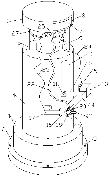
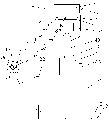
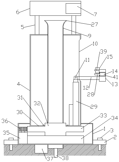
[0018] like figure 1 , 2 , As shown in 3 and 4, a robot intelligent refueling equipment includes a central fixed sleeve 9, the outer side of the bottom of the central fixed sleeve 9 is fixedly installed with a bottom stable support 34, and the center above the bottom stable support 34 The outer side of the fixed sleeve 9 is fitted with a rotary bearing 32, a rotary toothed disc 33 is fixedly installed on the circumferential direction of the rotary bearing 32, a bottom rotary motor 35 is fixedly installed on one side of the bottom stable support 34, and the output end of the bottom rotary motor 35 Fixedly connected with the bottom rotating gear 36, the rotating toothed disc 33 meshes with the bottom rotating gear 36, the rotating cylinder 4 is fixedly installed on the top of the rotating toothed disc 33, and the bottom outer side of the rotating cylinder 4 is fitted with a bottom protective shell 1. The top of the rotary cylinder 4 is provided with a limit hole, and the upper ...


PUM


Abstract

The invention relates to robot intelligent oiling equipment. One end of a transverse lifting rod is located in a center fixing sleeve, an inner connecting seat is fixedly mounted at the end, located in the center fixing sleeve, of the transverse lifting rod, the bottom of the inner connecting seat is fixedly connected with the output end of a lifting electric push rod, the bottom of the lifting electric push rod is fixedly connected with a rotary toothed disc, the other end of the transverse lifting rod is located outside the center fixing sleeve, a transverse supporting seat is fixedly mounted at the end, located outside the center fixing sleeve, of the transverse lifting rod, a transverse motion groove is formed in the transverse supporting seat, a transverse motion rod is movably mounted in the transverse motion groove, a transverse motion rod rotary gear is in engaged connection to a transverse motion rod tooth groove, and the transverse motion rod rotary gear is connected with theoutput end of a transverse motion rod motion motor fixedly mounted on the transverse supporting seat. The complex steps such as payment and oil quantity selection are reduced, and the oiling requirements of high-flow oiling vehicles can be met.

Description

technical field [0001] The invention relates to a robot intelligent refueling equipment. Background technique [0002] With the development of science and technology and the improvement of people's living standards, the number of cars used is increasing. In the process of using cars, it is inevitable to encounter refueling problems. At present, refueling mostly adopts the method of manual refueling. Although many gas stations have implemented self-service refueling, most gas stations are still equipped with operators to assist in refueling. Carry out refueling operations. When there are many refueling vehicles, it is difficult for fewer staff to take care of each refueling vehicle in an all-round way. If there are too many staff at the gas station, there will be a waste of human resources, and the efficiency of manual operation is relatively low. It is also low, and there will be work and operation errors, leading to safety accidents. In addition to payment operations, fu...

Claims


Application Information

Patent Timeline
IPC IPC(8): B25J11/00B67D7/04B67D7/06
CPCB25J11/00B67D7/04B67D7/06B67D7/0401B67D2007/0403B67D2007/0417
Inventor 林泽恩林茂松
Owner 河南英高能源科技有限公司
Why Eureka
Try Eureka