Lifting tool fulcrum rotary switching positioning mechanism

A positioning mechanism and fulcrum technology, applied in the direction of load hanging components, transportation and packaging, etc., can solve the problems of reduced work efficiency, fulcrum positioning errors, wax accumulation, etc., and achieve the effect of improving work efficiency and avoiding positioning errors

Pending Publication Date: 2019-11-29
DESIGN INST NO 9 MINISTRY OF MECHINE BUILDING
View PDF0 Cites 7 Cited by
  • Summary
  • Abstract
  • Description
  • Claims
  • Application Information

AI Technical Summary

Problems solved by technology

[0003] However, the positioning method in the prior art has certain limitations. The reason is that it is easy to cause positioning errors after the fulcrum is stressed, the positioning is not reliable, and it is not suitable for precise positioning.
And the structure is generally an open structure, which leads to wax accumulation, difficulty in cleaning, difficulty in rotation, and difficulty in setting the positioning hole of the fixture when used in the wax filling line
Unreliable positioning, prone to danger, seriously reducing work efficiency and affecting production beat

Method used


Image

  • Lifting tool fulcrum rotary switching positioning mechanism
  • Lifting tool fulcrum rotary switching positioning mechanism
  • Lifting tool fulcrum rotary switching positioning mechanism

Examples


Embodiment Construction

[0024] The present invention will be further described below in conjunction with the accompanying drawings; the embodiments described with reference to the accompanying drawings are exemplary, and are only used to explain the present invention, but cannot be construed as limiting the present invention.

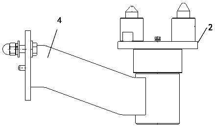
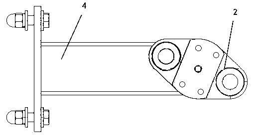
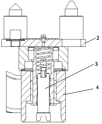
[0025] figure 1 Is a front view of a rotation positioning switching device provided by an embodiment of the present invention, figure 2 Is a top view of a rotation positioning switching device provided by an embodiment of the present invention, image 3 Is a schematic diagram of the rotating mechanism, Figure 4 Is a sectional view of the rotating part, Figure 5 To fix the mounting seat assembly to view, Image 6 Rotate the component to the view for the pivot point, Figure 7 Rotate the positioning component toward the view for the pivot point.

[0026] Such as Figure 1~Figure 7 As shown, a fulcrum rotation switching positioning mechanism of a spreader includes a fixed mounting b...


PUM


Abstract

The invention relates to a lifting tool fulcrum rotary switching positioning mechanism. The lifting tool fulcrum rotary switching positioning mechanism is characterized in that a fulcrum rotating assembly is connected with a fixed mounting seat, a sliding bearing is arranged in an inner cavity of the fixed mounting seat, a wearproof cushion is arranged on the upper end face and connected with thefulcrum rotating assembly, the fulcrum rotating assembly penetrates into the fixed mounting seat through a rotary center shaft, the inner side of the rotary center shaft is of a cavity structure, a long hole is formed in the wall of the rotary center shaft, a fulcrum rotary positioning assembly is fixed to a rotary shaft, the rotary shaft is connected to an inner cavity of the rotary center shaft,a positioning key slides on the long hole of the rotary center shaft, an end face and slope guider is arranged on the lower portion of the inner cavity of the fixed mounting seat, a connecting plateis arranged on one side of the fixed mounting seat and connected with a lifting tool arm, a long hole is formed in the connecting plate, and a rotary bracket is arranged on the other side of the fixedmounting seat. The lifting tool fulcrum rotary switching positioning mechanism is closed and compact in structure, and clamps are accurately positioned; and the safety of the positioning assembly isimproved, the working efficiency is improved, and the production takt is quickened.

Description

Technical field [0001] The invention relates to a fulcrum rotation switching positioning mechanism of a sling, in particular to a fulcrum rotation switching positioning mechanism for different models of the same sling, and belongs to the technical field of automobile coating wax filling line body sling design. Background technique [0002] The spreader design requirements for large-scale domestic automobile production lines are flexible. It is often necessary for the spreader to move or rotate through the fulcrum to meet the support requirements of different models. At this time, the fulcrum needs to be positioned after rotation. The existing positioning method is fulcrum rotation Afterwards, the positioning is performed by means of a knob plunger. When the position needs to be changed, a certain force is applied through the rotating device to make the fulcrum rotate a certain angle before positioning. [0003] However, the positioning method in the prior art has certain limitation...

Claims


Application Information

Patent Timeline
Patent Type & Authority Applications(China)
IPC IPC(8): B66C1/10B66C13/08
CPCB66C1/10B66C13/08
Inventor 朴永灿于广利黄大巍高先海曹辉
Owner DESIGN INST NO 9 MINISTRY OF MECHINE BUILDING
Why Eureka
Try Eureka