
Direct-drive permanent magnet synchronous wind power system and control method thereof

A permanent magnet synchronization and wind power system technology, applied in the direction of AC network voltage adjustment, single-network parallel feeding arrangement, etc., can solve problems such as unstable operation, large safety hazards, and failure to realize system fault ride-through

Inactive Publication Date: 2019-11-29
INNER MONGOLIA UNIV OF TECH
View PDF2 Cites 3 Cited by
  • Summary
  • Abstract
  • Description
  • Claims
  • Application Information

AI Technical Summary

Problems solved by technology

[0005] The purpose of the embodiment of the present invention is to provide a direct-drive permanent magnet synchronous wind power system, which aims to solve the common problems of unstable operation, large safety hazards and high system cost in the existing direct-drive permanent magnet synchronous wind power system, and the failure of the system cannot be realized The problem of crossing

Method used


Image

  • Direct-drive permanent magnet synchronous wind power system and control method thereof
  • Direct-drive permanent magnet synchronous wind power system and control method thereof
  • Direct-drive permanent magnet synchronous wind power system and control method thereof

Examples


Embodiment Construction

[0030] In order to make the object, technical solution and advantages of the present invention clearer, the present invention will be further described in detail below in conjunction with the accompanying drawings and embodiments. It should be understood that the specific embodiments described here are only used to explain the present invention, not to limit the present invention.

[0031] Terms used in the embodiments of the present invention are only for the purpose of describing specific embodiments, and are not intended to limit the present invention. As used in the embodiments of the present invention and the appended claims, the singular forms "a" and "the" are also intended to include plural forms unless the context clearly dictates otherwise. It should also be understood that the term "and / or" as used herein refers to and includes any and all possible combinations of one or more of the associated listed items.

[0032] It should be understood that although the terms f...


PUM


Abstract

The invention is applicable to the technical field of wind power generation, and provides a direct-drive permanent magnet synchronous wind power system and a control method thereof. The system comprises a wind turbine, a direct-drive permanent magnet synchronous wind generator set, a machine-side converter and a nine-switch converter. The nine-switch converter comprises an equivalent grid-side converter and an equivalent dynamic voltage restorer, and is used for converting a direct current output by the machine-side converter into an alternating current for grid connection. The equivalent grid-side converter is used for maintaining the stability of the direct-current side voltage. The equivalent dynamic voltage restorer is used for injecting a compensation voltage when the power grid fails. According to the system, the nine-switch converter is adopted to replace a grid-side converter in a direct-drive wind power system, the grid-connected operation and voltage compensation functions ofthe direct-drive permanent magnet synchronous wind generator set can be achieved, the direct-current voltage utilization rate of the converter is increased by adopting space vector pulse width modulation, and the design value of the direct-current side voltage is reduced.

Description

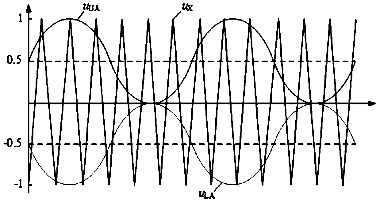
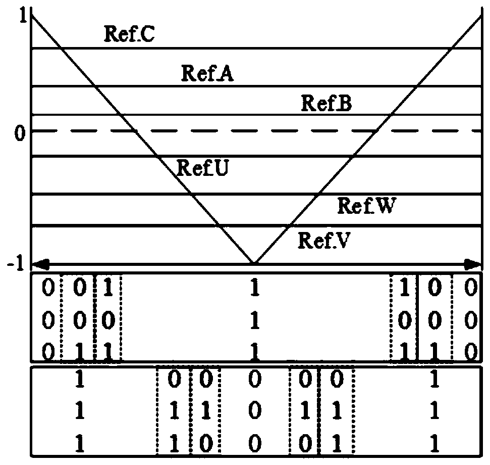
technical field [0001] The invention belongs to the technical field of wind power generation, and in particular relates to a direct-drive permanent magnet synchronous wind power system and a control method thereof. Background technique [0002] Direct-drive permanent magnet synchronous wind turbine (PMSG) is the mainstream direction of wind turbines due to its simple structure, low transmission loss, high reliability, and low maintenance cost. The direct drive permanent magnet synchronous wind power system is decoupled from the grid through the converter, so it has high low / high voltage ride through (LVRT / HVRT) capability. [0003] The LVRT of traditional PMSG wind turbines is mostly implemented by unloading circuits, but when an asymmetric fault occurs, the current will generate asymmetric components, which will affect the safe operation of the converter; The control strategy of LVRT solves the problem of LVRT by injecting reactive current to support grid voltage recovery ...

Claims


Application Information

Patent Timeline
Patent Type & Authority Applications(China)
IPC IPC(8): H02J3/38H02J3/12
CPCH02J3/12
Inventor 薛宇陈烁任永峰任宇
Owner INNER MONGOLIA UNIV OF TECH
Learn More