air conditioner

A technology for air conditioners and air supply fans, which is applied to air conditioning systems, mechanical equipment, machines/engines, etc., and can solve problems such as the easy deterioration of the fan cleaning part and the inability to fully clean the fan

Active Publication Date: 2020-09-01
HITACHI JOHNSON CONTROLS AIR CONDITIONING INC
View PDF7 Cites 0 Cited by
  • Summary
  • Abstract
  • Description
  • Claims
  • Application Information

AI Technical Summary

Problems solved by technology

Therefore, when the fan starts to rotate, a load is applied to the fan cleaning part, so that the fan cleaning part is likely to deteriorate, and if the fan cleaning part deteriorates, there is a problem that the fan cannot be cleaned sufficiently.

Method used


Image

  • air conditioner
  • air conditioner
  • air conditioner

Examples


Embodiment Construction

[0029] Embodiments for carrying out the present invention will be described in detail with reference to the drawings as appropriate.

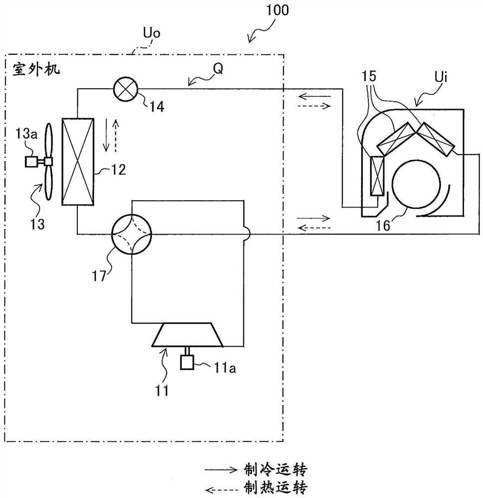
[0030] figure 1 It is an explanatory diagram showing the refrigerant circuit Q of the air conditioner 100 of the embodiment. figure 1 The solid line arrows in the arrows indicate the flow of the refrigerant during the heating operation. figure 1 The dotted arrows in the arrows indicate the flow of the refrigerant during the cooling operation. Such as figure 1 As shown, the air conditioner 100 includes a compressor 11 , an outdoor heat exchanger 12 , an outdoor fan 13 , and an expansion valve 14 . In addition, the air conditioner 100 includes an indoor heat exchanger (heat exchanger) 15 , an indoor fan (blower fan) 16 , and a four-way valve 17 in addition to the above-mentioned configuration.

[0031] The compressor 11 is a device that compresses a low-temperature and low-pressure gas refrigerant and discharges it as a high-temperature and h...


PUM


Abstract

The air conditioner (100) includes an indoor heat exchanger (15), an indoor fan (16), a fan cleaning unit (24) that cleans the indoor fan (16) with a brush (24b), and the fan cleaning unit (24) and A control unit (30) in contact with the indoor fan (16), the control unit (30) having a brush angle changing member (31b1) for changing the angle of the brush in contact with the indoor fan (16).

Description

technical field [0001] The present invention relates to air conditioners. Background technique [0002] As a technique for cleaning an indoor fan (fan) of an air conditioner, for example, Patent Document 1 describes a device including a "fan cleaning device for removing dust from a fan". Also, of Patent Document 1 figure 1 Describes a structure in which the fan cleaning device is installed near the air outlet of the indoor fan. [0003] prior art literature [0004] patent documents [0005] Patent Document 1: Japanese Patent No. 4046755 Contents of the invention [0006] The problem to be solved by the invention [0007] In the technique described in Patent Document 1, the fan cleaning portion comes into contact with the fan before the rotation of the fan starts. Therefore, when the fan starts to rotate, a load is applied to the fan cleaning unit, and the fan cleaning unit tends to deteriorate, and if the fan cleaning unit deteriorates, there is a problem that the f...

Claims


Application Information

Patent Timeline
Patent Type & Authority Patents(China)
IPC IPC(8): F24F1/0018F24F11/77F24F11/64F24F13/24B08B1/02
CPCB08B1/002B08B1/02F24F1/0018F24F13/24F24F2013/247F24F11/64F24F11/77F04D17/04F04D27/001F04D29/703F24F1/0025F24F2221/22Y02B30/70F24F13/22
Inventor 梅泽光加藤智大
Owner HITACHI JOHNSON CONTROLS AIR CONDITIONING INC
Why Eureka
Try Eureka