An automatic cutting machine for steel structure profile feeding and fixed length

A technology for cutting machinery and steel structures, applied in metal processing machinery parts, metal processing equipment, metal processing and other directions, can solve the problems of length adjustment of cutting plates, increase labor intensity of workers, and can not meet the requirements, achieve cutting optimization, and increase worker labor. Strength, good cutting effect

Active Publication Date: 2020-11-06
靖江市中元钢构有限公司
View PDF6 Cites 0 Cited by
  • Summary
  • Abstract
  • Description
  • Claims
  • Application Information

AI Technical Summary

Problems solved by technology

[0002] With the modernization process of society, there are more and more applications of steel. Among them, there are more and more demands and specifications for steel plates in various fields. Existing cutting machines are often only aimed at one kind of plate, or only output A plate, which is often unable to meet the actual needs of the factory
[0003] In the plate cutting process, there are the following problems. One, the cutting machine in the prior art cannot be adjusted to cut plates of different widths at the same time; Cause plate deformation, plate deformation will affect the accuracy of cutting, easy to make defective products in the plate, resulting in unnecessary losses; three, the cutting machine in the prior art when cutting the plate, it is easy to cause different lengths of the plate after cutting and it is impossible to adjust the length of the cut plate; 4. After the cutting machine in the prior art cuts the plate, the plate is often left on the platform and needs to be unloaded manually, which affects the efficiency and increases the labor intensity of the workers.

Method used


Image

  • An automatic cutting machine for steel structure profile feeding and fixed length
  • An automatic cutting machine for steel structure profile feeding and fixed length
  • An automatic cutting machine for steel structure profile feeding and fixed length

Examples


Embodiment Construction

[0023] In order to make the technical means, creative features, goals and effects achieved by the present invention easy to understand, the present invention will be further described below in conjunction with specific illustrations.

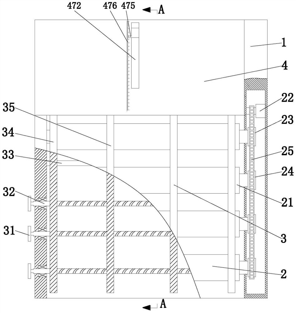
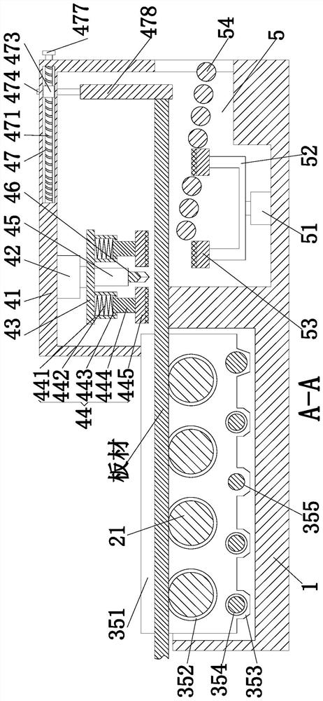
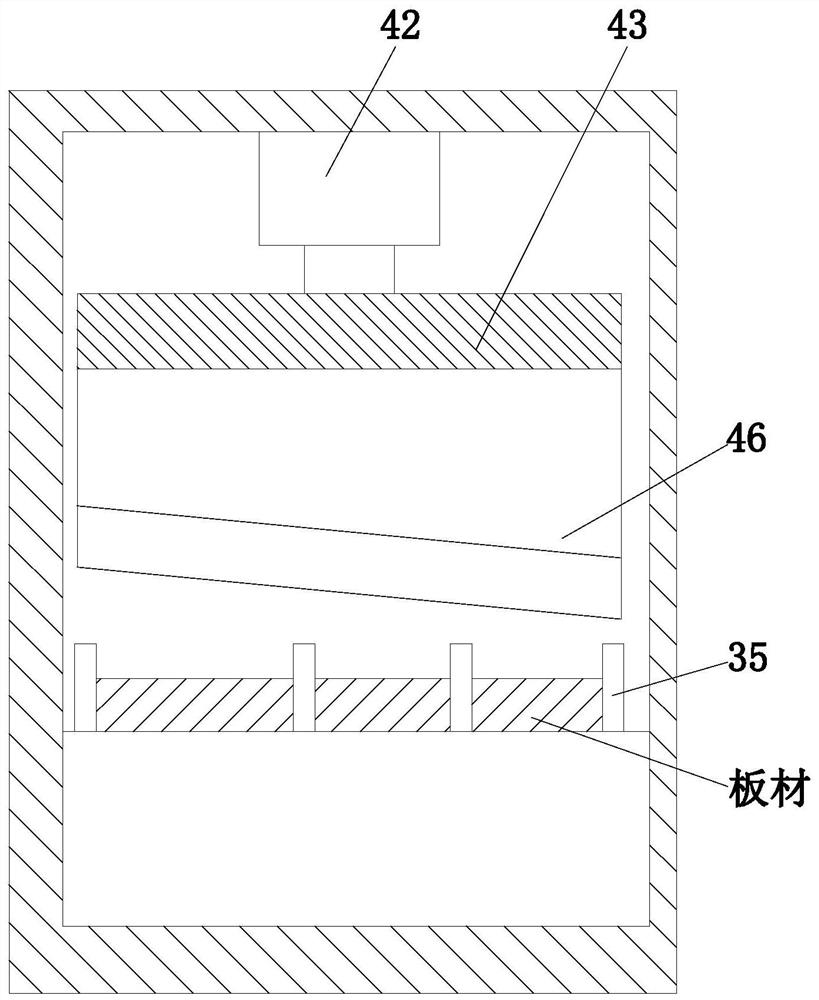
[0024] Such as Figure 1 to Figure 3 As shown in the figure, a steel structure profile feeding and fixed-length automatic cutting machine includes a base 1, a feeding device 2, a feeding device 3, a cutting device 4 and a cutting device 5, and the front end of the base 1 is set up from bottom to top. There are feeding chamber and unloading chamber, feeding device 2 and distributing device 3 are installed sequentially in the feeding chamber from top to bottom, cutting device 4 is installed on the upper side of the front end of base 1, and unloading device is installed in the unloading chamber 5. The feeding device 2 feeds the plate forward, the material distribution device 3 prevents the plate from deflecting, the cutting device 4 fixes the plate...


PUM


Abstract

The invention relates to a steel structure profile feeding fixed-length automatic cutting machine. The machine comprises a base, a feeding device, a material distributing device, a cutting device anda discharging device, a feeding cavity and a discharging cavity are formed in the front end of the base from bottom to top, the feeding device and the material distributing device are sequentially installed in the feeding cavity from top to bottom, the cutting device is installed on the upper side of the front end of the base, and the discharging device is installed in the discharging cavity; theadjustable material distributing plate is adopted, so that steel plates with different widths can be fed at the same time; by adjusting the position of the stop block, the steel plate cannot be fed after extending out by a specified length, and the cutting length of the steel plate is controlled; the two ends of the plate are prevented from tilting to influence the cutting precision in a mode of firstly fixing and then cutting; and through discharging of the plates, the conditions that the plates are accumulated on the working platform, efficiency is affected, and the labor intensity of workers is increased are prevented.

Description

technical field [0001] The invention relates to the technical field of cutting steel structure plates, in particular to an automatic cutting machine for steel structure profile feeding and fixed length. Background technique [0002] With the modernization process of society, there are more and more applications of steel. Among them, there are more and more demands and specifications for steel plates in various fields. Existing cutting machines are often only aimed at one kind of plate, or only output A plate, which is often unable to meet the actual needs of the factory. [0003] In the plate cutting process, there are the following problems. One, the cutting machine in the prior art cannot be adjusted to cut plates of different widths at the same time; Cause plate deformation, plate deformation will affect the accuracy of cutting, easy to make defective products in the plate, resulting in unnecessary losses; three, the cutting machine in the prior art when cutting the plat...

Claims


Application Information

Patent Timeline
Patent Type & Authority Patents(China)
IPC IPC(8): B23D79/00B23Q7/00B23Q5/34
CPCB23D79/00B23Q5/34B23Q7/00
Inventor 熊美俊郭含新郭寒生
Owner 靖江市中元钢构有限公司
Why Eureka
Try Eureka