Motor end cover plate machining auxiliary equipment

A technology of motor end cover and auxiliary equipment, applied in the direction of metal processing, etc., can solve the problems of low feeding efficiency, high labor intensity, heavy end cover plate weight, etc., and achieve the effect of low efficiency of change and improvement of processing efficiency

Active Publication Date: 2019-12-03
中擎电机有限公司
View PDF6 Cites 3 Cited by
  • Summary
  • Abstract
  • Description
  • Claims
  • Application Information

AI Technical Summary

Problems solved by technology

[0002] The motor end cover plate is a cover plate installed on the casing of the motor, and is provided with a mounting groove for installing a bearing socketed with the motor shaft. When processing the motor end cover plate, it needs to be processed by a lathe. Existing Most of the methods are manually loaded. Due to the inconsistent motor models, especially the heavy weight of the end cover plate of the larger motor, manual manual loading is labor-intensive and the feeding efficiency is low. In severe cases, it is easy to fall and smash accidents. , with the continuous improvement of the factory automation level, the existing feeding method can be adapted, so a motor end cover processing auxiliary equipment is needed

Method used


Image

  • Motor end cover plate machining auxiliary equipment
  • Motor end cover plate machining auxiliary equipment
  • Motor end cover plate machining auxiliary equipment

Examples


Embodiment 1

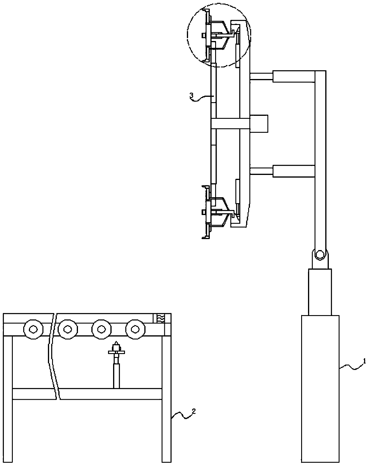
[0040] The second driving mechanism 102 adopts a linear module, and the first driving mechanism 302, the third driving mechanism 206 and the fourth driving mechanism 508 adopt any one of a linear motor, an air cylinder, and a hydraulic cylinder;

Embodiment 2

[0042] One end of the rotating rod 104 extending out of the movable plate 103 is fixedly connected with a second motor fixedly connected with the movable plate 103, and one end of the rotating shaft 304 extending out of the support plate 303 is fixedly connected with a third motor fixedly connected with the support plate 303;

Embodiment 3

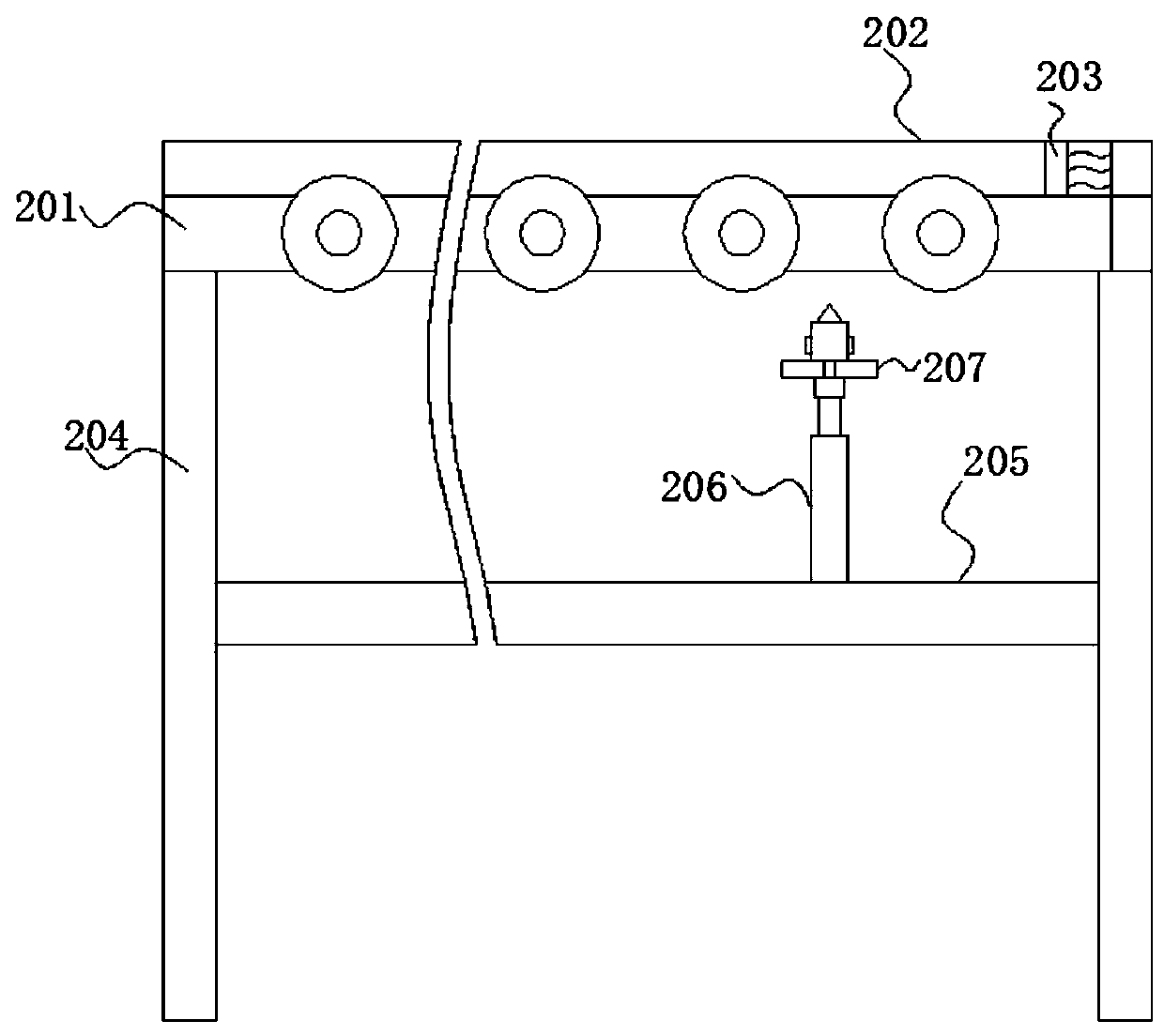
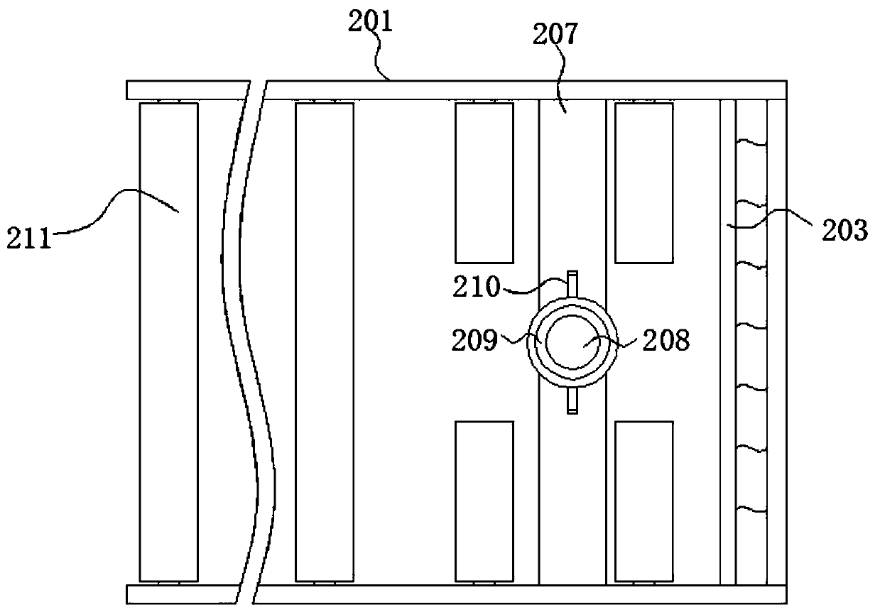
[0044] The transition groove 505 and the extruding block 507 are slidingly connected by means of slider guide rails, and the rollers 211 are connected by means of a chain sprocket, and the inner side walls of both sides of the opening of the blocking frame 202 are fixed with inclined guide rails. The side of the buffer plate 203 close to the push rod 208 is inlaid with a proximity switch, and the side of the push rod 208 away from the buffer plate 203 is equipped with a mechanical switch between adjacent rollers 211;

[0045] Such as Figure 8 Shown is the structural schematic diagram of the existing motor end cover:

[0046] Among them: including the cover plate body 601, the middle position of the cover plate body 601 is provided with a through hole 604, the end outer ring of the cover plate body 601 is provided with a chamfer 602 of circular arc structure, and the chamfer 602 is fixedly connected with a 601 is the edge 605 distributed in an axial array, and the outer ring ...


PUM


Abstract

The invention belongs to the technical field of motor processing, specially relates to motor end cover plate machining auxiliary equipment that comprises a conversion assembly with a swing plate; oneside of the swing plate is fixedly connected with a first driving mechanism perpendicular to the swing plate; the output end of the first driving mechanism is fixedly connected with a supporting discparallel to the swing plate. A switching mechanism used for switching and clamping the motor end cover plate is fixedly connected to the outer ring of the side, away from the swing plate, of the supporting disc; the center of the supporting disc is movably sleeved with a rotating shaft; extending plates distributed along the axis of the rotating shaft in an array mode are fixedly connected to theouter ring of the end, away from the swing plate, of the rotating shaft, and U-shaped connecting plates are fixedly connected to the ends, away from the rotating shaft, of the extending plates. According to the motor end cover plate machining auxiliary equipment, positioning, feeding and discharging operation during motor end cover plate machining is achieved, continuous production can be achievedin cooperation with a machine tool, the situations that a traditional manual feeding mode is low in efficiency and high in labor intensity, and potential safety hazards exist are changed, and the motor end cover plate machining efficiency is improved.

Description

technical field [0001] The invention relates to the technical field of motor processing, in particular to auxiliary equipment for processing motor end cover plates. Background technique [0002] The motor end cover plate is a cover plate installed on the casing of the motor, and is provided with a mounting groove for installing a bearing socketed with the motor shaft. When processing the motor end cover plate, it needs to be processed by a lathe. Existing Most of the methods are manually loaded. Due to the inconsistent motor models, especially the heavy weight of the end cover of the larger motor, manual manual loading is labor-intensive and the feeding efficiency is low. In serious cases, it is easy to fall and smash accidents. , with the continuous improvement of the factory automation level, the existing feeding method can be adapted, so a kind of auxiliary equipment for motor end cover processing is needed. Contents of the invention [0003] The auxiliary equipment fo...

Claims


Application Information

Patent Timeline
IPC IPC(8): B23Q7/04B23B15/00
CPCB23Q7/04B23Q7/048
Inventor 林波叶灵荣林娜金新兵叶云兰
Owner 中擎电机有限公司
Why Eureka
Try Eureka