Shot blasting, derusting, recycling and anti-pollution device for shot blasting machine

A shot blasting machine and anti-pollution technology, which is applied to used abrasive processing devices, grinding/polishing equipment, grinding machines, etc., can solve the problems of reducing rust removal, rust adhesion, and difficult removal, etc. To achieve the effect of guaranteed decontamination effect

Active Publication Date: 2019-12-03
绍兴市览海环保科技有限公司
View PDF7 Cites 2 Cited by
  • Summary
  • Abstract
  • Description
  • Claims
  • Application Information

AI Technical Summary

Problems solved by technology

[0004] The working process of the shot blasting machine is that the numerical control intelligent method throws the shot at a high speed and a certain angle so that the shot hits the surface of the plate that needs to be derusted, and then cleans the inside of the machine through the airflow of the matching vacuum cleaner. The shot material and the cleaned impurities are recovered separately. However, when the shot blasting machine performs derusting work, the steel shot will hit the plate, and the surface of the steel shot will have rust stains, and the rust will be due to the strong impact between the steel shot and the plate. , tightly adhered to the steel shot, and it is not easy to remove. After the steel shot is recovered, it needs to enter the steel shot machine again to continue the derusting process. Therefore, when the steel shot with rust attached to the plate collides again, the rust on the steel shot will It will adhere to the plate again, reducing the effect of rust removal

Method used


Image

  • Shot blasting, derusting, recycling and anti-pollution device for shot blasting machine
  • Shot blasting, derusting, recycling and anti-pollution device for shot blasting machine
  • Shot blasting, derusting, recycling and anti-pollution device for shot blasting machine

Examples


Embodiment Construction

[0020] The following will clearly and completely describe the technical solutions in the embodiments of the present invention with reference to the accompanying drawings in the embodiments of the present invention. Obviously, the described embodiments are only some, not all, embodiments of the present invention. Based on the embodiments of the present invention, all other embodiments obtained by persons of ordinary skill in the art without making creative efforts belong to the protection scope of the present invention.

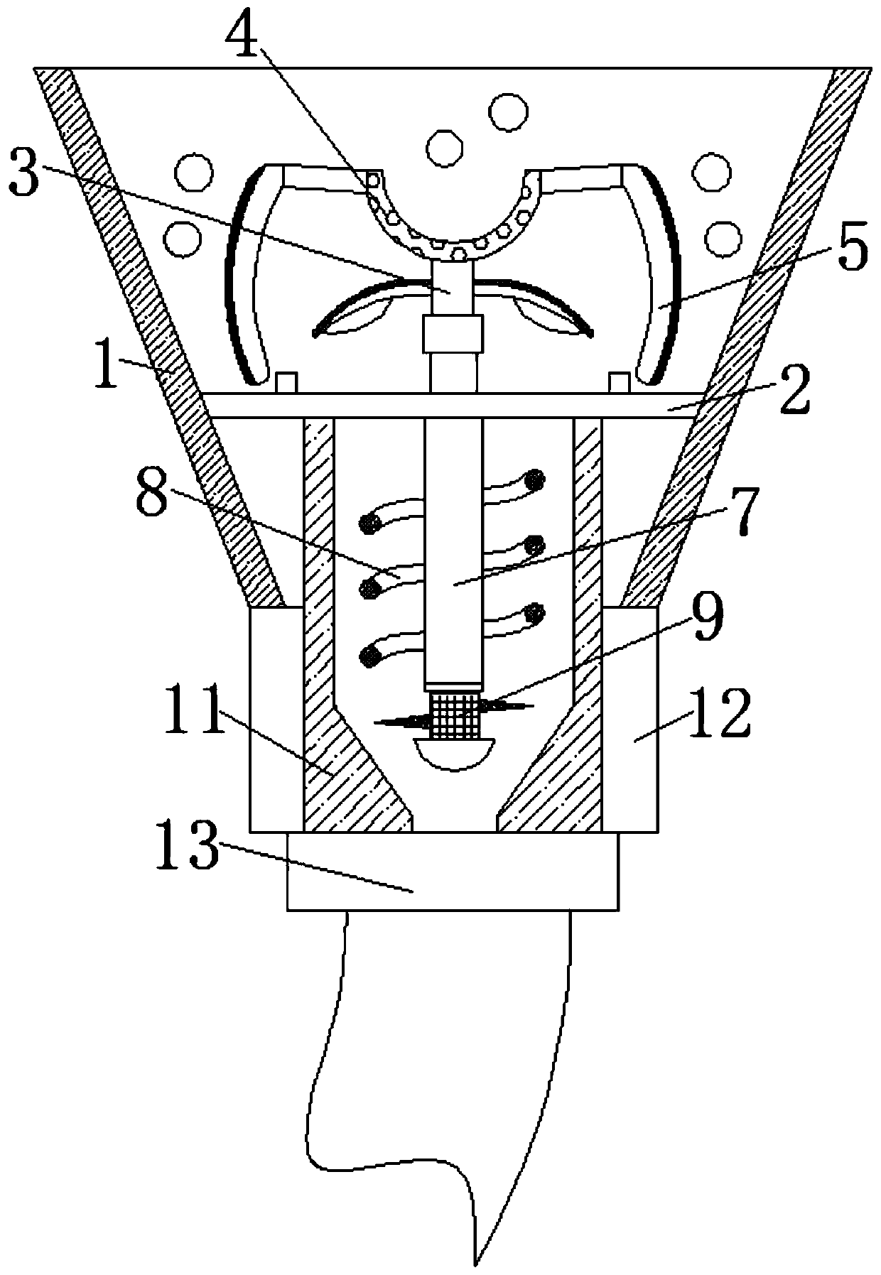
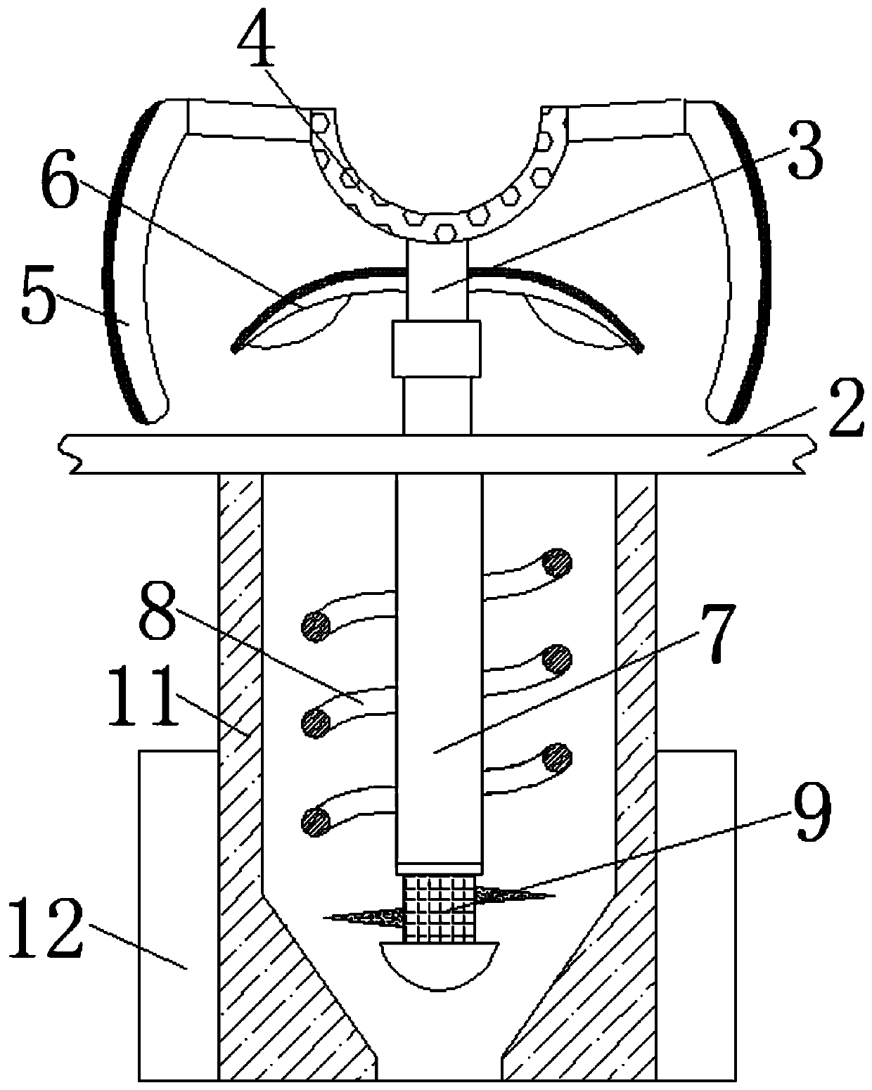
[0021] see Figure 1-3 , a kind of anti-pollution device for shot blasting and rust removal for shot blasting machine, comprising: storage box 1, the inside of storage box 1 is fixedly equipped with leaking plate 2, and the upper surface of leaking plate 2 is fixedly installed with fixing, mainly for allowing The steel shots dropped on the drain plate 2 through the grinding plate 6 are scattered everywhere. The upper surface of the drain plate 2 is fixedly equ...


PUM


Abstract

The invention relates to the technical field of shot blasting machines, and discloses a shot blasting, derusting, recycling and anti-pollution device for a shot blasting machine. The device comprisesa storage box, a bushing is fixedly mounted in the storage box, and a rotating rod is fixedly mounted on the upper surface of the bushing; an arc plate is fixedly mounted at the upper end of the rotating rod, the polishing blocks are hinged to the two ends of the arc plate, and a polishing plate is fixedly installed at the middle end of the rotating rod; a fixing rod is fixedly installed on the lower surface of the bushing, a barrier strip is fixedly installed outside the fixing rod, and a magnetic column is movably installed at the lower end of the blocking strip; the check blocks are fixedlyinstalled at the two sides of the magnetic column, a fixing shell is fixedly installed on the lower surface of the bushing, and a fixing block is fixedly installed at the lower end of the fixing shell. Through the cooperative use of the fixing rods, the barrier strip, the magnetic columns and the check blocks, the rust powder on the outer surfaces of the derusted steel shots can be effectively removed, and the situation that the rust powder attached to the outer surfaces of the derusted steel shots collides with the plate again, and the plate is polluted, is avoided.

Description

technical field [0001] The invention relates to the technical field of shot blasting machines, in particular to a shot blasting rust removal and reuse pollution prevention device for shot blasting machines. Background technique [0002] Shot blasting machine is a processing technology that uses numerical control intelligence to drop steel sand and steel shot at high speed and impact on the surface of material objects, while shot blasting machine hits the surface of the metal through one or more sand materials, thereby eliminating some of the attached particles on the surface. In addition, sometimes a specific surface layer can also be obtained by blasting the metal surface with a shot blasting machine. [0003] At present, the outer surface of most existing iron products is easily oxidized into iron tetroxide in the air. In order to prolong the service life of the plate, it is generally put into a shot blasting machine for derusting after rusting, and then this will be remov...

Claims


Application Information

Patent Timeline
Patent Type & Authority Applications(China)
IPC IPC(8): B24B27/033B24C9/00
CPCB24B27/033B24C9/006
Inventor 刘小会
Owner 绍兴市览海环保科技有限公司
Why Eureka
Try Eureka