Supercharge Your Innovation With Domain-Expert AI Agents!

Foaming box tool

A foaming box and tooling technology, which is applied in the direction of lifting devices, transmission devices, lifting frames, etc., can solve the problems of insufficient depth of screw grooves, reduced output power of foaming boxes, and foaming of heavy-weight devices, etc., to achieve Save maintenance efficiency, improve output power, and save maintenance cost

Inactive Publication Date: 2019-12-03
ANHUI XINMENG EQUIP CO LTD
View PDF7 Cites 2 Cited by
  • Summary
  • Abstract
  • Description
  • Claims
  • Application Information

AI Technical Summary

Problems solved by technology

[0003] At present, most of the foaming tools use ball screws when lifting the foaming box, and the driving motor is also lifted with the lifting of the foaming box. In this way, when the motor is lifted together with the foaming box At this time, because part of the output power of the motor is used to lift itself, the output power to the foaming box is reduced, and the ball screw structure is rolled along the screw because the balls circulate back and forth, and the depth of the spiral groove of the screw is not enough. Deep, once the weight of the foaming box is too large, it is easy to cause power instability, which is not suitable for foaming of large-weight devices

Method used


Image

  • Foaming box tool
  • Foaming box tool
  • Foaming box tool

Examples


Embodiment Construction

[0037] The application will be further described in detail below with reference to the drawings and embodiments. It can be understood that the specific embodiments described here are only used to explain the related invention, but not to limit the invention. In addition, it should be noted that, for ease of description, only the parts related to the invention are shown in the drawings.

[0038] It should be noted that the embodiments in the application and the features in the embodiments can be combined with each other if there is no conflict. Hereinafter, the present application will be described in detail with reference to the drawings and in conjunction with embodiments.

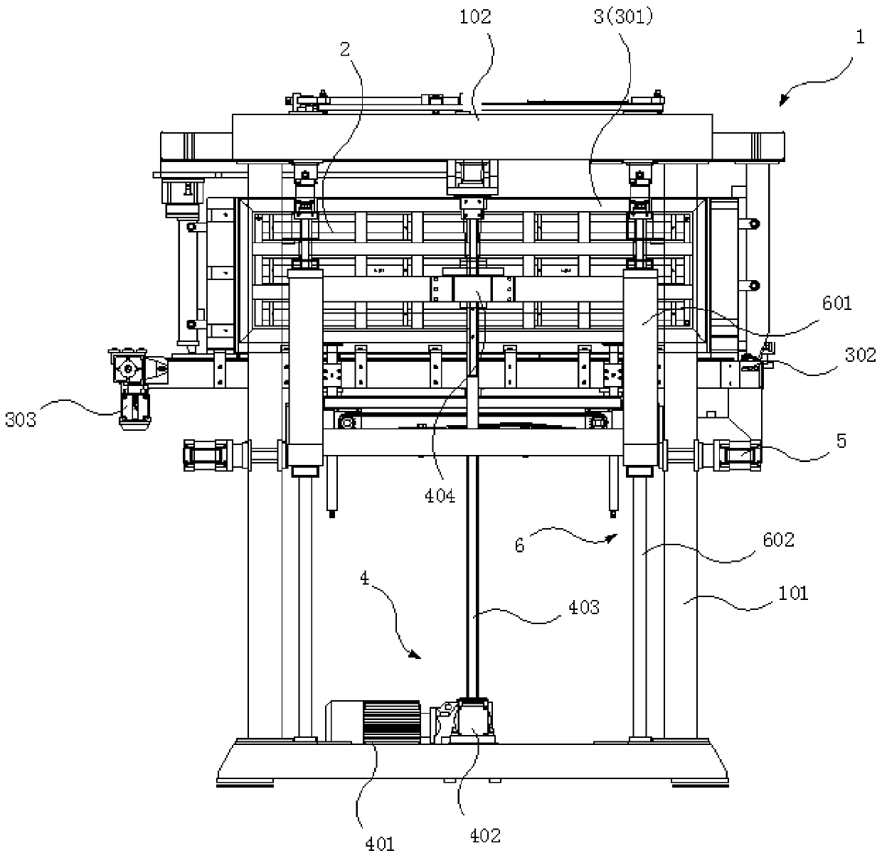
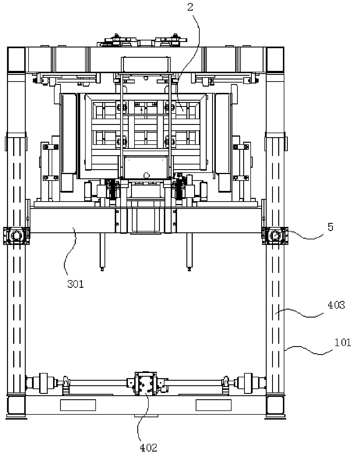
[0039] Such as figure 1 , 2 As shown, the present invention discloses a foaming box tooling, including a frame 1. A loading mechanism 3 for loading the foaming box 2 is installed on the frame 1, and a loading mechanism 3 for driving the loading mechanism 3 to move up and down is also installed on the frame 1....


PUM


Abstract

The invention discloses a foaming box tool which comprises a machine frame, a loading mechanism used for loading a foaming box is installed on the machine frame, a lifting driving mechanism used for driving the loading mechanism to move up and down is further installed on the machine frame, and the machine frame comprises four stand columns defining a rectangle and a fixing plate fixedly installedat the tops of the four stand columns. The lifting driving mechanism comprises a second driving motor, a reversing mechanism, a screw rod and a transmission block; a plurality of spiral grooves distributed along a screw rod body are formed in the screw rod; the transmission block comprises a hexagonal prism body with a central hole; fixing grooves with the same specification are formed in the hole wall of the central hole, fixing blocks are fixedly connected into the fixing grooves respectively, vertically-distributed balls are installed on the fixing blocks and embedded in the outer side surfaces of the fixing blocks, and when the transmission block is matched with the screw rod, spiral grooves of the screw rod are filled with the parts, exposed out of the embedding grooves, of the ballsto lock the lifting frame. When the foaming box is lifted, high output power is achieved, the bearing capacity is high, and power output is stable and reliable.

Description

Technical field [0001] The invention relates to a foaming technology, in particular to a foaming box tooling. Background technique [0002] Usually in the foaming process of the box, the process from the initial stage to the foaming stage of the foaming box is to first send the foaming box into the foaming tooling, and to lift the foaming box to the designated position through the foaming tooling. Then close the foaming box, and finally start the foaming mechanism to foam the device to be foamed in the foaming box. It can be seen that the entire process is carried out in the foaming tooling. Therefore, the quality of the foaming tooling affects the foaming quality. [0003] At present, most of the foaming tooling uses ball screws when lifting the foaming box, and the drive motor is also lifted with the lifting of the foaming box. In this way, when the motor is lifted with the foaming box At the same time, part of the output power of the motor is used to improve itself, which lead...

Claims


Application Information

Patent Timeline
Patent Type & Authority Applications(China)
IPC IPC(8): B66F7/14B66F7/28B66F3/08B66F3/44F16H25/22
CPCB66F3/08B66F3/44B66F7/14B66F7/28B66F2700/04F16H25/2204
Inventor 王强刘征高振
Owner ANHUI XINMENG EQUIP CO LTD
Features
  • R&D
  • Intellectual Property
  • Life Sciences
  • Materials
  • Tech Scout
  • Unparalleled Data Quality
  • Higher Quality Content
  • 60% Fewer Hallucinations
Learn More