
Common rail device and common rail fuel system

A technology of common rail and common rail pipe, which is applied in the direction of charging system, fuel injection device, engine components, etc., and can solve the problems of large volume, low fuel compressibility, and difficult layout

Pending Publication Date: 2019-12-03
CSSC POWER INST CO LTD
View PDF0 Cites 1 Cited by
  • Summary
  • Abstract
  • Description
  • Claims
  • Application Information

AI Technical Summary

Problems solved by technology

[0002] The operation of a diesel engine is inseparable from the normal operation of the fuel system. The high-pressure common rail fuel system represents the most advanced fuel injection technology, and the high-pressure common rail device plays a vital role in stabilizing the fuel injection pressure in the fuel system. The current The high-pressure common rail device utilizes the compressibility of the liquid, and by constructing a larger liquid chamber, after the fuel is sprayed out of the high-pressure common rail device, the pressure fluctuation of the high-pressure common rail fuel system can be stabilized within the allowable range, but due to the The compressibility is very small, so usually the high-pressure common rail device needs to be manufactured into a relatively large volume, and it will be difficult to arrange it on some small-volume diesel engines

Method used


Image

  • Common rail device and common rail fuel system
  • Common rail device and common rail fuel system
  • Common rail device and common rail fuel system

Examples


Embodiment Construction

[0029] Embodiments of the present invention are described in detail below, and examples of the embodiments are shown in the drawings, wherein the same or similar reference numerals denote the same or similar elements or elements having the same or similar functions throughout. The embodiments described below by referring to the figures are exemplary and are intended to explain the present invention and should not be construed as limiting the present invention.

[0030] In the description of the present invention, unless otherwise clearly specified and limited, the terms "connected", "connected" and "fixed" should be understood in a broad sense, for example, it can be a fixed connection, a detachable connection, or an integrated ; It can be a mechanical connection or an electrical connection; it can be a direct connection or an indirect connection through an intermediary, and it can be the internal communication of two components or the interaction relationship between two compo...


PUM


Abstract

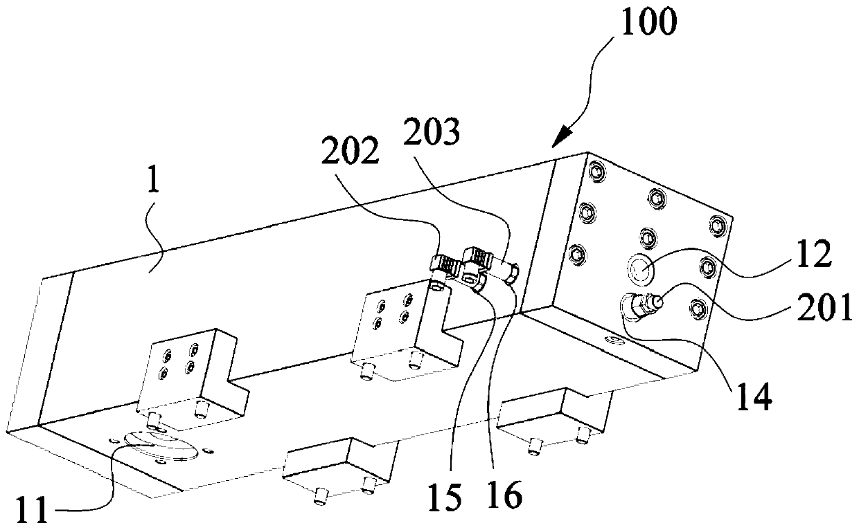
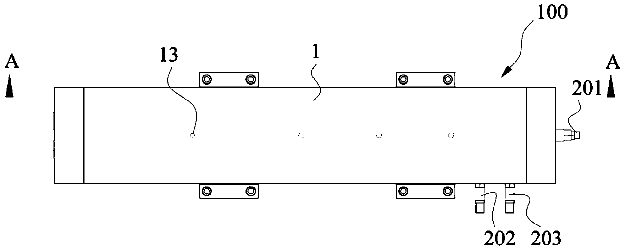
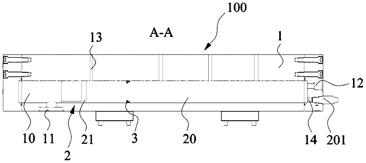
The invention discloses a common rail device and a common rail fuel system, and relates to the technical field of diesel engines. The common rail device includes a common rail tube; a common rail cavity is formed in the common rail tube; a pressure accumulation assembly is further included, the pressure accumulation assembly is arranged in the common rail cavity and can move in the length direction of the common rail cavity. The pressure accumulation assembly divides the common rail cavity into a first closed cavity and a second closed cavity, the first closed cavity is configured to contain apressure accumulation gas medium, the second closed cavity is configured to contain a fuel medium, and the pressure accumulation assembly is configured to balance the pressure in the common rail cavity through movement in the common rail tube. The common rail device is good in pressure stabilization, smaller in size and higher in adaptability. The common rail fuel system comprises an oil supply device and an oil injection device and further comprises the common rail device; the oil supply device and the oil injection device are both connected with the common rail device, and the common rail fuel system is higher in integration degree and adaptability.

Description

technical field [0001] The invention relates to the technical field of diesel engines, in particular to a common rail device and a common rail fuel system. Background technique [0002] The operation of a diesel engine is inseparable from the normal operation of the fuel system. The high-pressure common rail fuel system represents the most advanced fuel injection technology, and the high-pressure common rail device plays a vital role in stabilizing the fuel injection pressure in the fuel system. The current The high-pressure common rail device utilizes the compressibility of the liquid, and by constructing a larger liquid chamber, after the fuel is sprayed out of the high-pressure common rail device, the pressure fluctuation of the high-pressure common rail fuel system can be stabilized within the allowable range, but due to the The compressibility is very small, so usually the high-pressure common rail device needs to be manufactured into a relatively large volume, and it w...

Claims


Application Information

Patent Timeline
Patent Type & Authority Applications(China)
IPC IPC(8): F02M55/02F02M55/04
CPCF02M55/025F02M55/04
Inventor 方良杰牛军军张全富
Owner CSSC POWER INST CO LTD
Learn More