
Steel ball spacer ring of linear transmission device

A technology of linear transmission and spacer rings, which is applied to transmission devices, belts/chains/gears, mechanical equipment, etc., and can solve problems such as increased material costs, unfixable spacing, and separation

Active Publication Date: 2019-12-03
HIWIN TECH
View PDF8 Cites 0 Cited by
  • Summary
  • Abstract
  • Description
  • Claims
  • Application Information

AI Technical Summary

Problems solved by technology

[0003] However, in order to make the screwing of the first member and the second member stable, the first member must The thickness of the internal thread section of the second member and the external thread section of the second member increases, resulting in an increase in the cost of the material and reducing the number of effective steel balls in the circulation path
In addition, the above-mentioned way of screwing the internal and external threads may cause the first member and the second member to rotate relative to each other due to the rolling friction of the rolling elements (steel balls), so that the distance between them cannot be fixed, or even situation of separation

Method used


Image

  • Steel ball spacer ring of linear transmission device
  • Steel ball spacer ring of linear transmission device
  • Steel ball spacer ring of linear transmission device

Examples


Embodiment Construction

[0035] In order to describe the structure and features of the present invention in detail, the following preferred embodiments are now described with accompanying drawings as follows:

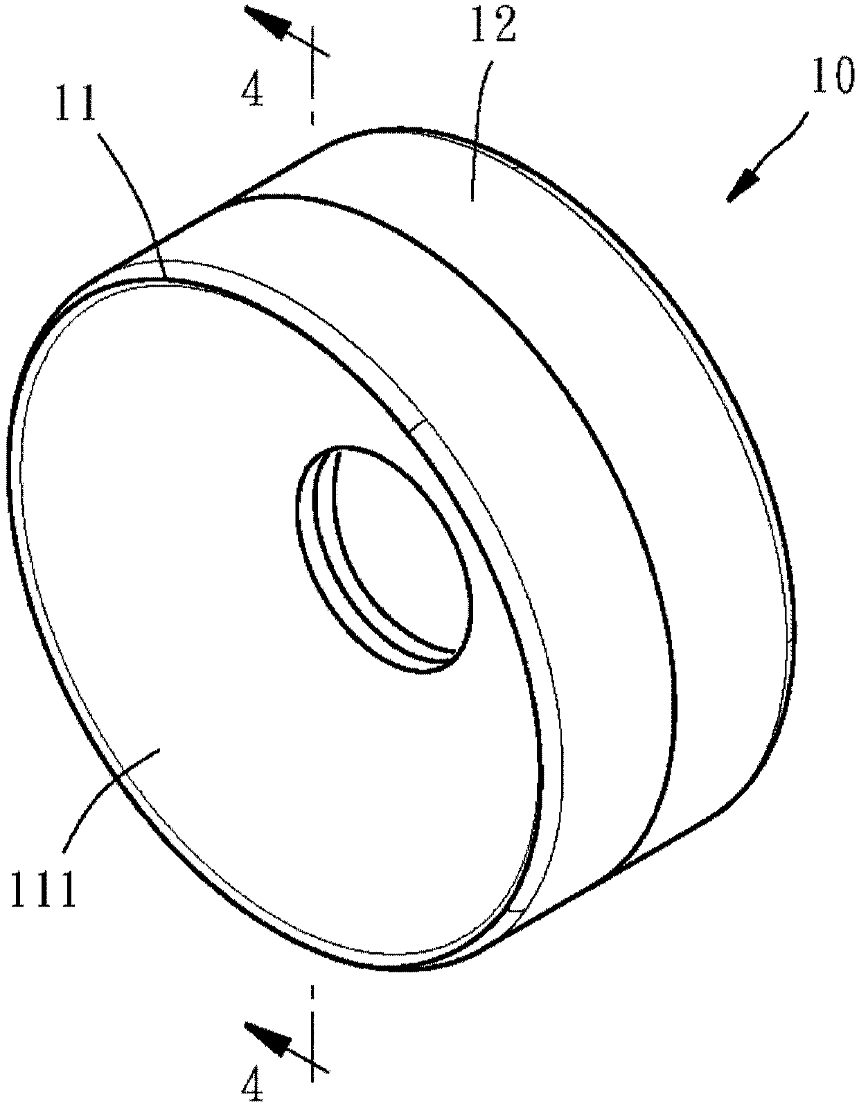
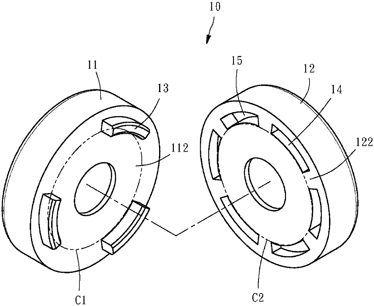
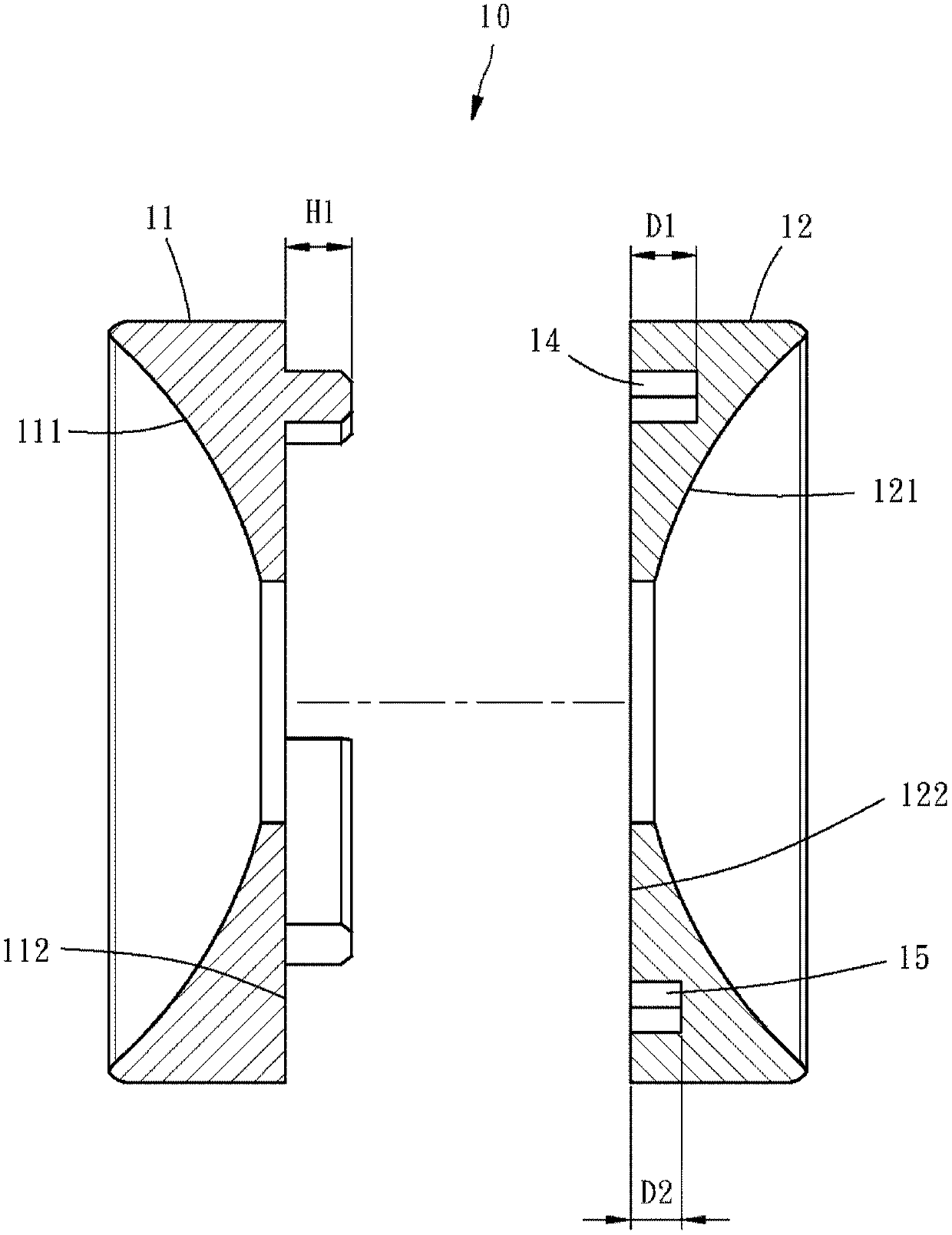
[0036] refer to Figure 9 , a steel ball spacer ring 10 of a linear transmission device in the present invention is used to be placed in the circulation path 100 of the linear transmission device and between two rolling elements 200, so that the circulation path 100 is filled, and the Linear actuators can be ball screws, bearings, linear slides, roller screws, etc. The embodiment of the present invention is illustrated by using a general ball screw. The ball screw of the aforementioned linear transmission device includes a long shaft and a moving body that can slide on the long shaft. The long shaft and the moving body belong to the prior art and are not The main technical features of the present invention will not be repeated here, nor shown on the drawings. The rolling elements 200 are steel...


PUM


Abstract

A steel ball spacer ring of a linear transmission device comprises a plurality of spacers, and the effect of adjusting the thickness of the steel ball spacer ring is achieved through the mutual matching of the convex parts arranged on the spacers and a plurality of concave parts with different depths.

Description

technical field [0001] The invention relates to components of a linear transmission device, in particular to a steel ball spacer ring of a linear transmission device. Background technique [0002] China Taiwan Patent No. 1491817 discloses a transmission element with an adjustable spacer, and the adjustable spacer includes a first component and a second component. The first member has a first retaining surface at one end and a groove at the other end, and an internal thread is provided in the groove. The second component has a second retaining surface at one end and a projection at the other end, and the projection has an external thread that can be screwed with the internal thread. By screwing the internal thread and the external thread of the first member and the second member, the first member or the second member can be rotated relatively, the distance between the first holding surface and the second holding surface can be adjusted, and the distance can also be adjusted....

Claims


Application Information

Patent Timeline
Patent Type & Authority Applications(China)
IPC IPC(8): F16H25/22
CPCF16H25/2204
Inventor 杨家铭吴政翰孙溢隆庄裕纬
Owner HIWIN TECH
Learn More