Fracture-cavity oil and gas reservoir fractured well large karst cave well testing interpretation method

A technology for well test interpretation and fracturing wells, applied in wellbore/well components, earthwork drilling and production, instruments, etc., can solve the problems of limited application range, inability to solve well test problems of fracturing oil and gas reservoirs, and incomplete multi-media continuity Assumptions and other questions

Active Publication Date: 2019-12-03
SOUTHWEST PETROLEUM UNIV
View PDF5 Cites 21 Cited by
  • Summary
  • Abstract
  • Description
  • Claims
  • Application Information

AI Technical Summary

Problems solved by technology

However, these models have simple fracture-cavity combinations and limited scope of application, so they cannot be applied to fracture-vuggy reservoirs in fractured wells.
In the production practice of fracture-cavity reservoirs, there are production wells that do not encounter effective fracture-cavity areas, resulting in low productivity of oil wells
To sum up, the assumption of incomplete multi-media continuity in fractured-cavity reservoirs with large-scale fractures and caves, and the existing drilling-encountered karst-cavity model and fracture-cavity combination well testing model cannot solve the problem of well testing in fractured reservoirs.

Method used


Image

  • Fracture-cavity oil and gas reservoir fractured well large karst cave well testing interpretation method
  • Fracture-cavity oil and gas reservoir fractured well large karst cave well testing interpretation method
  • Fracture-cavity oil and gas reservoir fractured well large karst cave well testing interpretation method

Examples


Embodiment Construction

[0152] The present invention will be further described below in conjunction with accompanying drawing, protection scope of the present invention is not limited to the following:

[0153] A well test interpretation method for large karst caves in fracturing wells in fractured-cavity reservoirs, comprising the following steps:

[0154] S1. Establishment of physical model for well testing of fracturing wells:

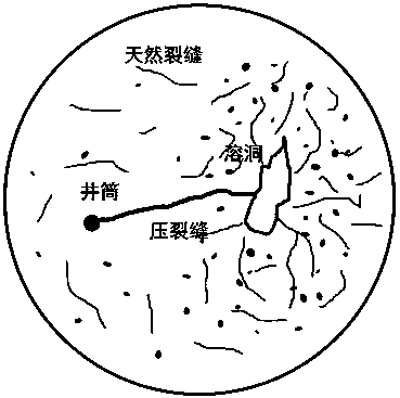
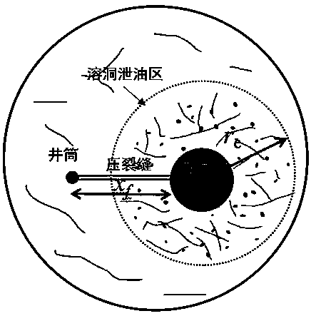
[0155] In radial reservoirs, production wells are connected to large caves through fractures, and there is a dual-media drainage area centered on the caves, such as figure 1 A schematic diagram of a fractured well reservoir is shown; the basic assumptions of the physical model are as follows:

[0156] (1) The oil drainage area is formed with the cave as the center, and there are continuously distributed natural fractures and dissolved pores outside the cave, which are regarded as a continuous medium; (2) There is a vertical well in the formation that produces at a constan...


PUM


Abstract

The invention discloses a fracture-cavity oil and gas reservoir fractured well large karst cave well testing interpretation method. The method comprises the following steps: S1, establishing a fractured well fracture-cavity oil reservoir well testing physical model; s2, establishing a karst cave and karst cave oil drainage area radial seepage dimensionless mathematical model; s3, establishing a fracture linear seepage dimensionless mathematical model and a coupling model of the fracture linear seepage dimensionless mathematical model and the radial seepage model; s4, enabling the mathematicalmodel to be subjected to Laplace transformation and solving; s5, drawing a typical well testing double logarithm curve; s6, fitting explanation of actual test well data; s7, researching the influenceof the radius of the karst cave; and S8, researching the influence of the main fracture length. The beneficial effects of the invention are that: a fracture-cavity oil and gas reservoir fractured welllarge karst cave well test interpretation method is established; a large-scale fracturing crack seepage channel is formed by considering shaft fracturing; the pressure crack is communicated with thelarge karst cave; a large-scale karst cave is regarded as a potential body, a double-medium karst cave oil drainage area is formed with the karst cave as the center, a mathematical model is established through radial seepage of the karst cave oil drainage area and linear flow coupling of a fracturing fracture, Laplace transformation solving is conducted on the model, a typical well testing double-logarithm curve is drawn, and parameter sensitivity analysis is conducted on the model.

Description

technical field [0001] The invention relates to the technical field of geological exploration, in particular to a well test interpretation method for fracturing wells in fracture-cave oil and gas reservoirs. Background technique [0002] There are a large number of natural fractures, dissolved pores and large-scale dissolved caves in fractured-vuggy reservoirs, and these three types of media are good oil and gas storage spaces. The current seismic identification and drilling techniques cannot fully guarantee that fractured-cavity reservoirs will be encountered. In the case that production wells do not encounter karst caves, measures such as fracturing are often used to generate artificial fractures to communicate with effective fracture-cavity reservoirs. For such fractured-cavity reservoirs with fractured wells, identifying the volume of dissolved caves and the length of fractures has important guiding significance for guiding later production. [0003] Since the 1960s, m...

Claims


Application Information

Patent Timeline
Patent Type & Authority Applications(China)
IPC IPC(8): G06F17/50E21B49/00
CPCE21B49/00
Inventor 刘建仪刘治彬刘学利邹宁黄知娟
Owner SOUTHWEST PETROLEUM UNIV
Why Eureka
Try Eureka