Integrated acetic acid enemator
An enema, integrated technology, applied in the direction of enema/irrigator, infusion set, syringe, etc., can solve the problems of time-consuming, laborious, inconvenient operation, etc., and achieve the effect of reducing intestinal HP, saving labor costs, and improving treatment time.
- Summary
- Abstract
- Description
- Claims
- Application Information
AI Technical Summary
Problems solved by technology
Method used
Image
Examples
Embodiment 1
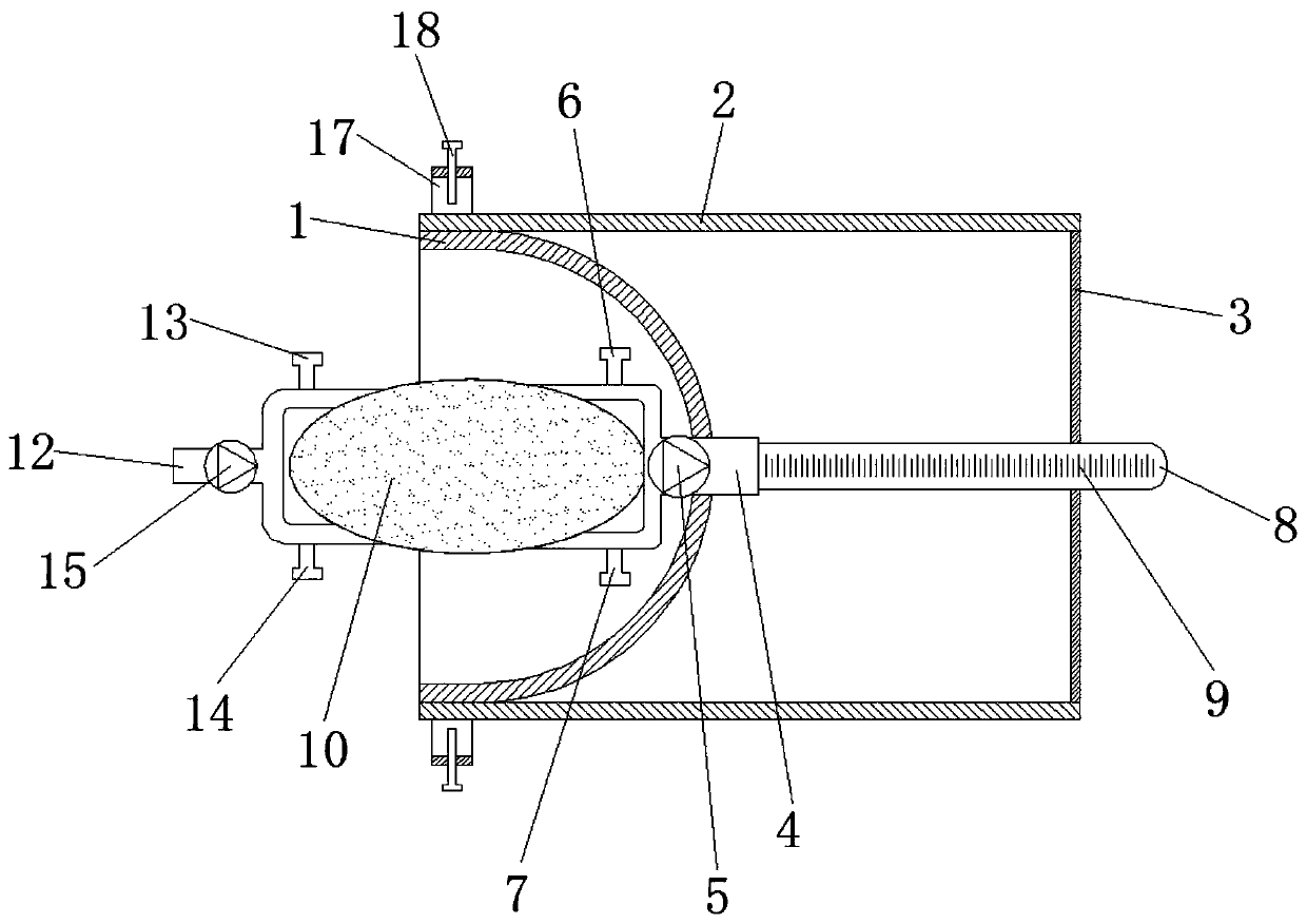
[0024] Such as figure 1 As shown, the integrated acetic acid enema device includes a cover body 1, a liquid discharge mechanism, a liquid storage mechanism, a liquid inlet mechanism, a slide bar 2, a limit plate 3, and a fixing mechanism. The liquid discharge mechanism is fixed on the cover body 1 In the middle end of the interior, the liquid storage mechanism is fixedly set on the left side of the liquid discharge mechanism, the liquid inlet mechanism is fixed on the left side inside the liquid storage mechanism, and the slide bar 2 is slidably arranged on the outside of the cover body 1 up and down At both ends, the limiting plate 3 is fixed on the right side between two slide bars 2 , and the fixing mechanism is fixed on the upper and lower ends of the outside of the cover body 1 .
[0025] In this one-piece acetic acid enema device, the medical personnel first inject the acetic acid solution from the liquid inlet mechanism into the inner lower end of the liquid storage mec...
Embodiment 2
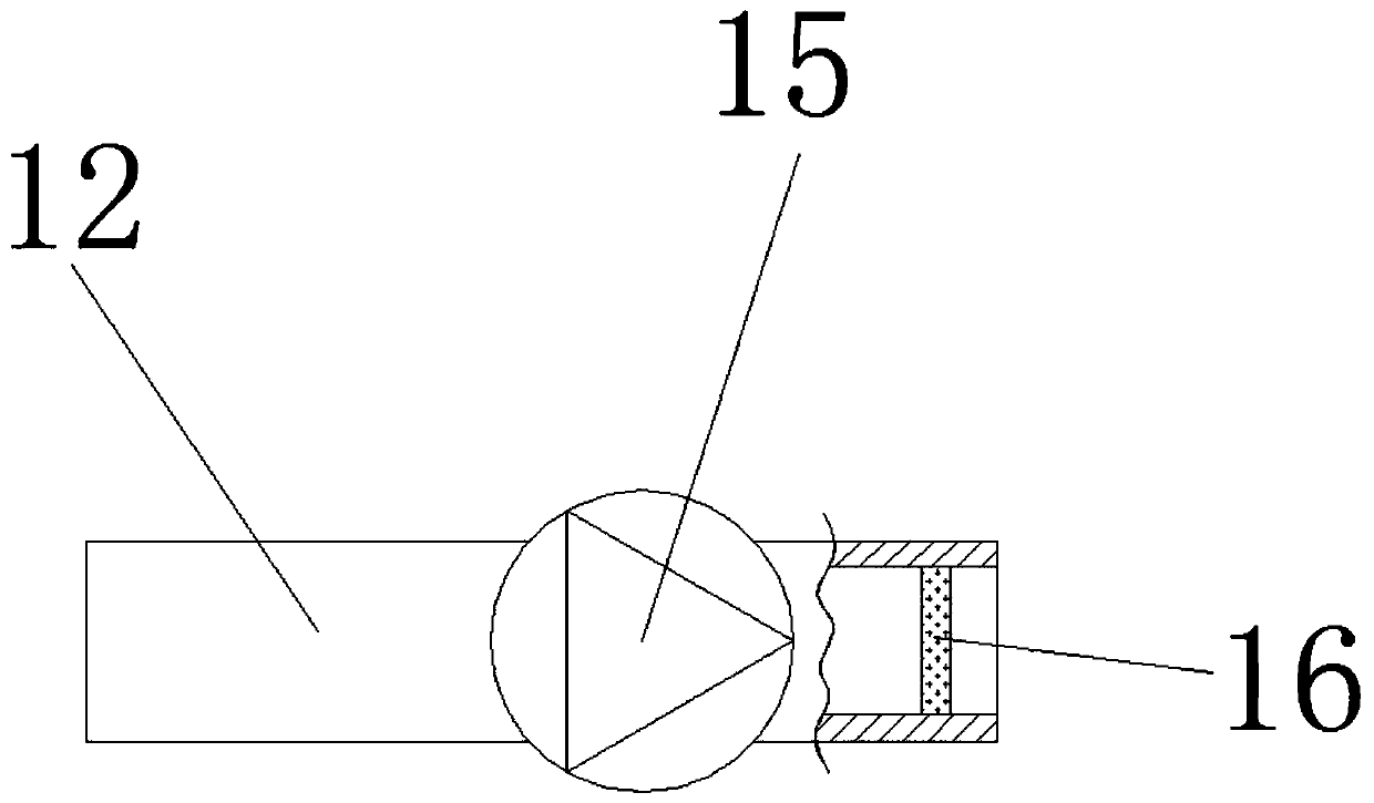
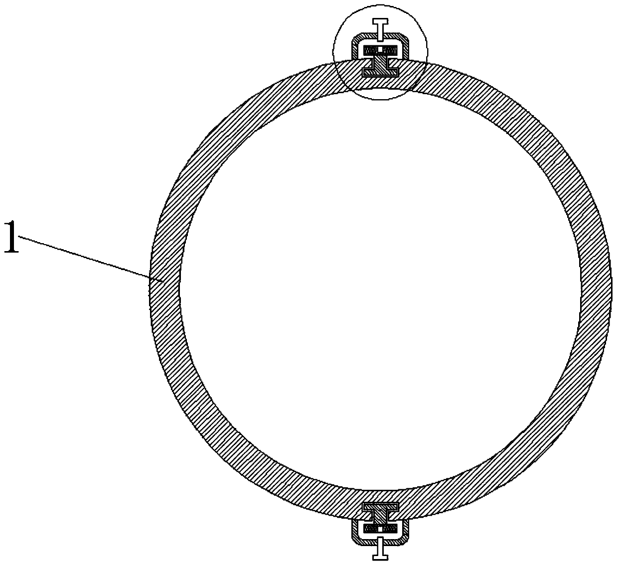
[0027] Such as figure 1 , figure 2 , image 3 , Figure 4 , Figure 5 As shown, the integrated acetic acid enema device includes a cover body 1, a liquid discharge mechanism, a liquid storage mechanism, a liquid inlet mechanism, a slide bar 2, a limit plate 3, and a fixing mechanism. The liquid discharge mechanism is fixed on the cover body 1 In the middle end of the interior, the liquid storage mechanism is fixedly set on the left side of the liquid discharge mechanism, the liquid inlet mechanism is fixed on the left side inside the liquid storage mechanism, and the slide bar 2 is slidably arranged on the outside of the cover body 1 up and down At both ends, the limiting plate 3 is fixed on the right side between the two slide bars 2, the fixing mechanism is fixed on the upper and lower ends of the outside of the cover body 1, and the draining mechanism is formed by a Y-shaped joint 4 , a first one-way valve 5, a first valve 6, a second valve 7, a conduit 8 and a scale 9...
PUM
 Abstract
Description
Claims
Application Information
 - R&D
- Intellectual Property
- Life Sciences
- Materials
- Tech Scout
- Unparalleled Data Quality
- Higher Quality Content
- 60% Fewer Hallucinations
Browse by: Latest US Patents, China's latest patents, Technical Efficacy Thesaurus, Application Domain, Technology Topic, Popular Technical Reports.
© 2025 PatSnap. All rights reserved.Legal|Privacy policy|Modern Slavery Act Transparency Statement|Sitemap|About US| Contact US: help@patsnap.com


