Support structure for vehicle and manufacturing method thereof

A technology for structures and vehicles, which is applied in the direction of manufacturing tools, vehicle parts, steering mechanisms, etc., can solve problems such as hindering weight reduction, and achieve the effect of weight reduction

Active Publication Date: 2022-06-24
HITACHI ASTEMO LTD
View PDF6 Cites 0 Cited by
  • Summary
  • Abstract
  • Description
  • Claims
  • Application Information

AI Technical Summary

Problems solved by technology

In other words, the base side of the rib has to increase the wall thickness, which leads to the formation of redundant walls unnecessary in terms of strength on the rib, preventing weight reduction

Method used


Image

  • Support structure for vehicle and manufacturing method thereof
  • Support structure for vehicle and manufacturing method thereof
  • Support structure for vehicle and manufacturing method thereof

Examples


Embodiment Construction

[0035] Hereinafter, embodiments of the present invention will be described in detail.

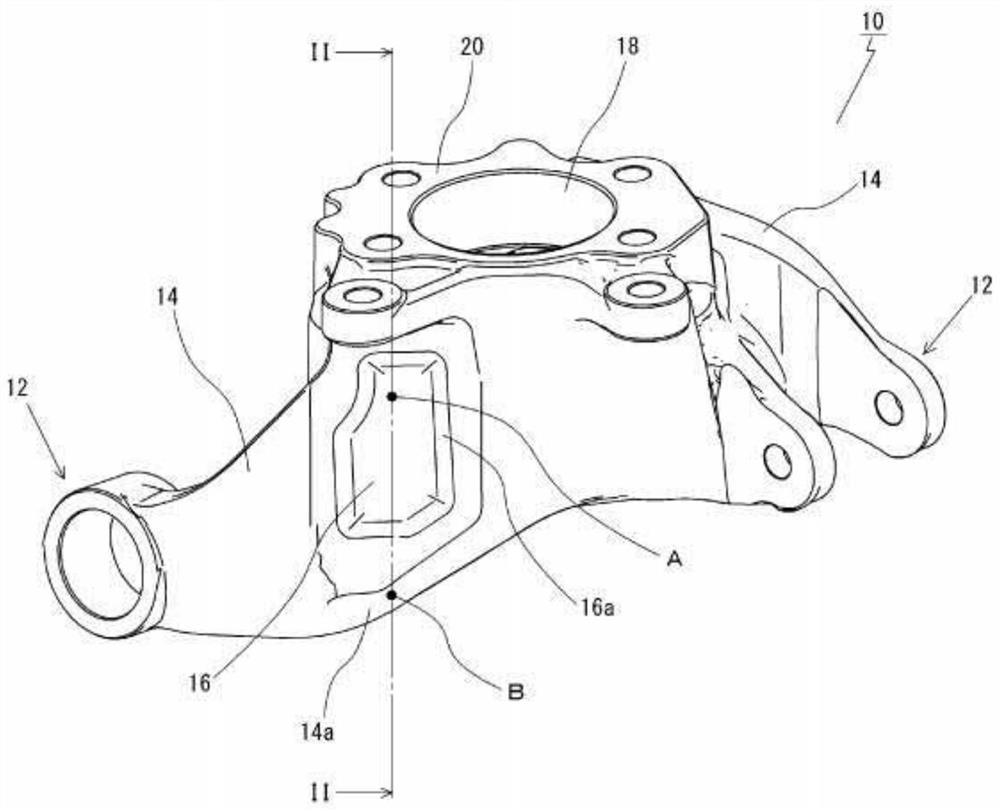
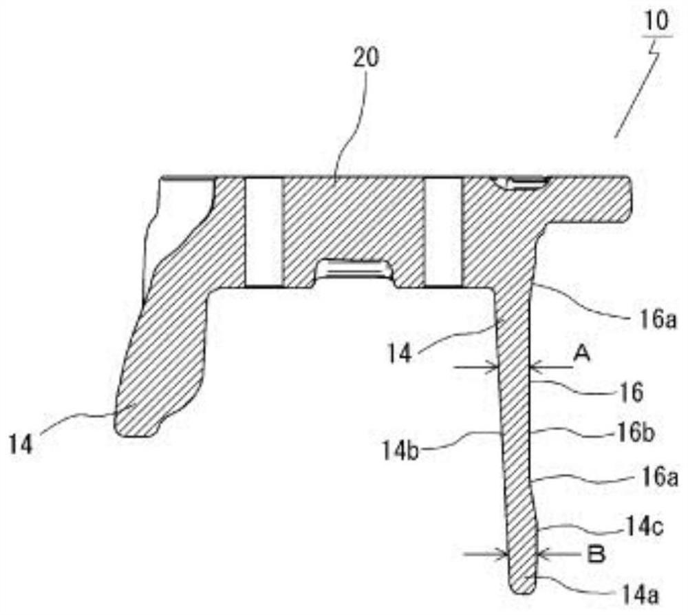
[0036] figure 1 is a perspective view of a steering knuckle 10 showing an example of a vehicle support structure, figure 2 Yes figure 1 Section II-II.

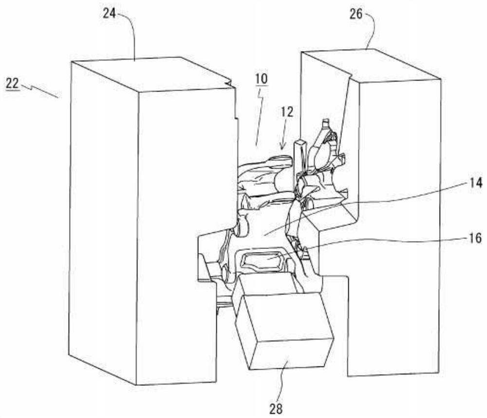
[0037] The steering knuckle 10 according to the embodiment of the present invention is formed by a casting mold as described above, is provided between the vehicle body and the vehicle component, and has the support portion 12 that supports the vehicle component, and the rib formed continuously with the support portion 12 . 14 is characterized in that the side surface portion of the rib 14 has a punch portion 16 recessed in a direction different from the parting direction of the casting mold.

[0038] The steering knuckle 10 is a member that transmits the transmission force from the steering device to the wheels. More specifically, the steering knuckle 10 has a complex deformed shape having a main body 20 and the support portion 12, whe...


PUM


Abstract

The present invention provides a supporting structure for a vehicle and a manufacturing method thereof, which can achieve weight reduction. The vehicle support structure (10) is formed by a casting mold (22) and is arranged between the vehicle body and the vehicle parts, and has a support part (12) supporting the vehicle part and a rib formed continuously with the support part 12 ( 14) A casting punch (16) recessed in a direction different from the parting direction of the casting mold (22) is provided on the side surface of the rib (14).

Description

technical field [0001] The present invention relates to a vehicle support structure capable of achieving weight reduction and a method for manufacturing the same. Background technique [0002] A steering knuckle (vehicle support structure) is a member that transmits a transmission force from a steering device to a wheel, and as shown in Patent Document 1 (Japanese Patent Laid-Open No. 2013-144488 ) and the like, the steering knuckle has a main body and a support portion. A complex deformed shape in which the main body has a cylindrical fitting hole for fitting and fixing the axle (bearing), and the support portion is connected to the periphery of the main body via a rib, and connects and supports the upper suspension, lower suspension, and steering knuckle Vehicle parts on the vehicle body side such as arms. [0003] Patent Document 1: Japanese Patent Laid-Open No. 2013-144488 [0004] As described above, the knuckle often forms a rib when connecting the plurality of suppo...

Claims


Application Information

Patent Timeline
Patent Type & Authority Patents(China)
IPC IPC(8): B62D7/18B22D18/02
CPCB62D7/18B22D18/02B22C9/22B60G2206/50B60G2206/8101
Inventor 寺田和弘丸山泰宏
Owner HITACHI ASTEMO LTD
Why Eureka
Try Eureka