Connecting piece inner insertion type steel pipe column and steel beam connection joint

A technology for connecting nodes and connectors, applied in the direction of buildings and building structures, can solve the problems of complex welding seam intersection, affecting the beauty of buildings, damage to the mechanical performance of nodes, etc., to achieve superior bending performance, simple force transmission mechanism, The effect of simplifying the installation process

Pending Publication Date: 2019-12-06
SOUTH CHINA UNIV OF TECH
View PDF0 Cites 4 Cited by
  • Summary
  • Abstract
  • Description
  • Claims
  • Application Information

AI Technical Summary

Problems solved by technology

[0004] (1) When the column section is small, it is difficult to construct the inner diaphragm welded in the inner diaphragm joint steel pipe, and it is not easy to ensure the quality of the connecting weld
[0005] (2) The outer clapboard joint significantly increases the section size of the column at the joint, which affects the aesthetics of the building and may cause a waste of building space
[0006] (3) The partition penetrating joint needs to break the column member in the joint area, which affects the integrity of the column member. If there is a problem with the quality of the weld, it will cause unimaginable damage to the structure
[0007] (4) Beam-end stiffened joints need to weld complex joints such as angle steel and T-shaped steel in the beam-column connection area. damage

Method used


Image

  • Connecting piece inner insertion type steel pipe column and steel beam connection joint
  • Connecting piece inner insertion type steel pipe column and steel beam connection joint
  • Connecting piece inner insertion type steel pipe column and steel beam connection joint

Examples


Embodiment 1

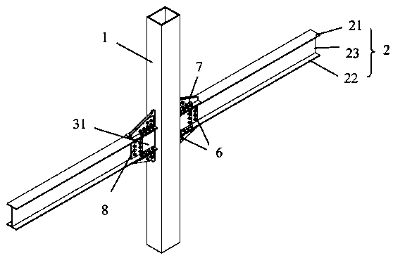
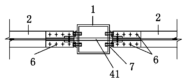
[0040] Such as figure 1 , figure 2 As shown, the connection node of the internally inserted steel pipe column and the steel beam includes a steel pipe column 1, a steel beam 2 and a connecting piece. The connecting piece is arranged vertically, and the connecting piece horizontally penetrates the steel pipe column 1 and protrudes from the side wall of the steel pipe column 1. The connecting piece is welded to the flange of the steel pipe column 1, that is, the connecting piece is welded at the junction of the steel pipe column 1. The steel beam 2 is arranged on one side of the connecting piece, the web 23 of the steel beam 2 is arranged vertically, and the flanges of the steel beam 2 are respectively connected with The upper part and the lower part of the piece are connected by high-strength bolts 6, and the web 23 of the steel beam 2 is connected with the high-strength bolt 6 in the middle of the connecting piece.

[0041] Specifically, the steel pipe column 1 is horizontally pr...

Embodiment 2

[0058] The structure of this example is roughly the same as that of Example 1, but the differences are:

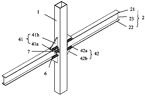
[0059] Such as image 3 , Figure 4 As shown, the cross section of the steel tube column 1 is rectangular or square, and the form is a hollow steel tube column 1 or a concrete-filled steel tube concrete composite column. The web 23 of the steel beam 2 and the side wall of the steel pipe column 1 are connected by an angle steel 7.

[0060] The connector includes an upper inner insert 41 and a lower inner insert 42, the upper inner insert 41 is located above the lower inner insert 42, and the upper inner insert 41 includes an upper flange connecting plate 41a and an upper vertical plate 41b that are perpendicular to each other. The lower end of the upper vertical plate 41b is connected to The middle of the upper flange connecting plate 41a is fixed; the lower inner insert 42 includes a lower flange connecting plate 42a and a lower vertical plate 42b that are perpendicular to each...

Embodiment 3

[0074] The structure of this example is roughly the same as that of Example 2, but the differences are:

[0075] Such as Figure 5 , Image 6 As shown, the connecting piece includes an upper connecting piece and a lower connecting piece. The upper connecting piece and the lower connecting piece respectively penetrate the steel pipe column 1 horizontally and protrude from the side wall of the steel pipe column 1, and the upper connecting piece is provided with an upper groove horizontally passing through the upper connecting piece. The lower connecting piece is provided with a lower groove that horizontally penetrates the lower connecting piece. The extension direction of the upper groove and the lower groove is parallel to the axial direction of the steel beam 2, that is, the extension of the upper groove and the lower groove The direction is parallel to the length of the steel beam 2. The flange of the steel beam 2 includes an upper flange 21 and a lower flange 22. The upper groo...


PUM


Abstract

The invention relates to a connecting piece inner insertion type steel pipe column and steel beam connection joint which comprises a steel pipe column, a steel beam and a connecting piece; the connecting piece is vertically arranged, horizontally penetrates through the steel pipe column, protrudes out of the side wall of the steel pipe column and is welded to flanges of the steel pipe column; thesteel beam is correspondingly arranged on one side of the connecting piece; a web plate of the steel beam is vertically arranged; the flanges of the steel beam are connected with high-strength bolts at the upper part and the lower part of the connecting piece respectively; and the web plate of the steel beam is connected with high-strength bolts at the middle part of the connecting piece. During welding, the section size of the steel pipe column is not limited, the welding difficulty is small, and the integrity of a column member is not affected; all welding is completed in a steel structure processing plant, and bolt connection needs to be completed at a construction site only, so that the field installation procedure is simplified, the bending resistance is excellent, the force transmission mechanism is simple, the bearing capacity is high, the ductility performance is good, the energy consumption capability is strong, and the design requirements for a strong node and a weak member can be met.

Description

Technical field [0001] The invention relates to the field of construction engineering, in particular to the connection node of an internally inserted steel pipe column and a steel beam of a connector. Background technique [0002] my country's steel structure industry is developing rapidly. Steel structures and steel-concrete composite structures are lightweight, high-strength, ductile, and highly reliable. They have good energy-saving characteristics, stress performance, and seismic performance. They have strong modeling capabilities, high industrialization, and economic benefits. High, it is favored by engineers and architects at home and abroad, and is widely used in multi-high-rise buildings, super high-rise buildings, industrial buildings, large stadiums and public infrastructure. [0003] At present, the connection forms of rectangular steel pipe column-steel beam joints at home and abroad mainly include diaphragm joints, beam end stiffening joints, and penetrating joints, but...

Claims


Application Information

Patent Timeline
Patent Type & Authority Applications(China)
IPC IPC(8): E04B1/24E04B1/58
CPCE04B1/2403E04B2001/2406
Inventor 潘建荣王鹏李彬王湛蔡昊龙
Owner SOUTH CHINA UNIV OF TECH
Why Eureka
Try Eureka