Impulse-type grouting apparatus with variable voltage variable frequency

A grouting device and a pulsed technology, applied in the field of pulsed grouting devices, can solve problems such as the inability to provide grouting pressure, and achieve the effects of flexible and adjustable grouting mode, high grouting frequency, and increased discharge speed

Active Publication Date: 2019-12-06
CHINA UNIV OF GEOSCIENCES (BEIJING) +1
View PDF10 Cites 3 Cited by
  • Summary
  • Abstract
  • Description
  • Claims
  • Application Information

AI Technical Summary

Problems solved by technology

[0003] The current grouting equipment can realize grouting pressure control under constant pressure, but cannot provide a stable grouting pressure during pulsating grouting
At the same time, the grouting time and interval time of the current pulsating pressure are both greater than 2 seconds, which cannot provide higher frequency grouting pressure

Method used


Image

  • Impulse-type grouting apparatus with variable voltage variable frequency
  • Impulse-type grouting apparatus with variable voltage variable frequency
  • Impulse-type grouting apparatus with variable voltage variable frequency

Examples


Embodiment 1

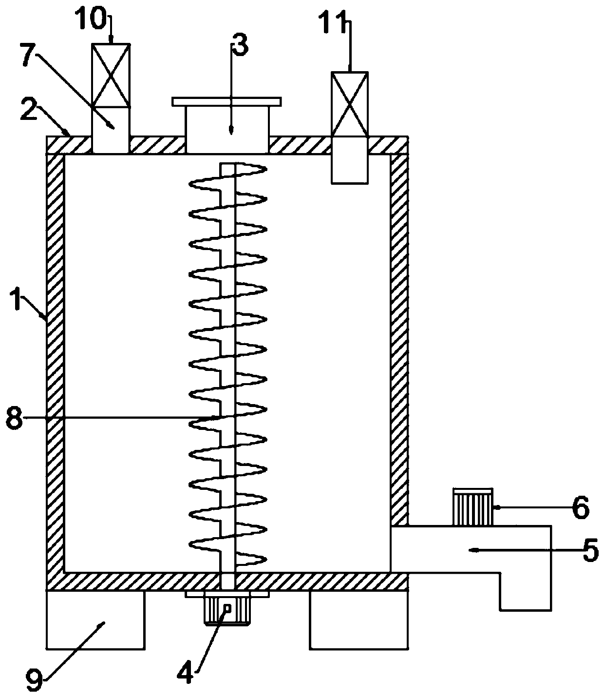
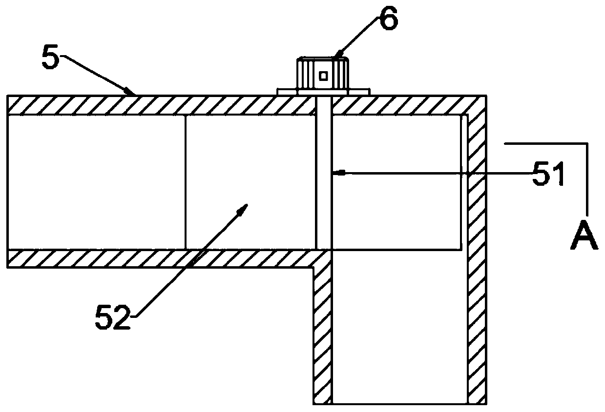
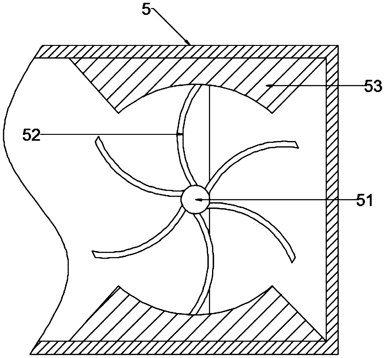
[0025] see Figure 1~3 , in an embodiment of the present invention, a pulse type grouting device with variable frequency and variable pressure includes a cylinder body 1, on which the upper cover 2 is movable assembled by riveting, and the upper cover 2 is connected with a The grouting pipe 3, the lower end of one side of the cylinder body 1 is also connected with the grouting pipe 5, and the upper cover 2 is also connected with two sets of pressure control valves 7 that limit the flow direction and are used for pressure regulation. The pressure valves 7 are all connected to the inside and outside of the cylinder body 1, and the upper ends of the two groups of pressure control valves 7 are respectively connected with an exhaust fan 10 and a blower fan 11, and the cylinder body 1 is also connected with a homogeneous structure for stirring. The grout pipe 5 is also provided with a valve structure to control the flow rate through rotation, and the valve structure is driven by the...

Embodiment 2

[0032] see Figure 4~5 , in the embodiment of the present invention, a pulse type grouting device with variable frequency and variable pressure. The blockage structure in the trachea 71 is composed of a fixed bracket 72 fixedly connected to one end of the air guide tube 71, and the fixed bracket 72 is connected to the blockage structure through an elastic member 74; the blockage structure includes a sliding fit arranged on the guide tube The sliding bracket 73 in the trachea 71 and the sealing gasket 76 connected by the connecting rod 75, the fixed bracket 72 and the sliding bracket 73 are all cross-shaped structures, and the sealing gasket 76 diameter and the outer circumference of the end of the airway tube 71 are The diameters are matched, and the sealing gasket 76 and the end of the airway tube 71 are attached with a cushion layer on the opposite side. The sealing gasket 76 is movably attached to the end surface of the airway tube 71 when the elastic member 74 has no exter...


PUM


Abstract

The present invention discloses an impulse-type grouting apparatus with variable voltage variable frequency. The apparatus comprises a barrel. An upper cover is movably assembled on the barrel in a riveting manner, and an inlet pipe is disposed on the upper cover in a through connection manner. A lower end of one side of the barrel is further communicated with a grouting pipe. Two groups of pressure control valves that are used for limiting flow directions and adjusting pressures are further disposed and connected on the upper cover. Both the two groups of pressure control valves are communicated with inside and outside of the barrel. Further, upper ends of the two groups of pressure control valves are respectively communicated with a suction fan and an air blower. A homogeneous structureused for stirring is further disposed and connected inside the barrel. A valve structure that controls a flow speed through rotation is further disposed inside the grouting pipe, and the valve structure drives operation by using a second motor connected on the grouting pipe. According to the impulse-type grouting apparatus, a driving speed of the second motor can be adjusted to control a sizing agent discharging speed, and the sizing agent discharging speed can also be controlled by starting the suction fan or the air blower. Materials can be discharged under cooperation, and an impulse-type grouting effect can be formed as required.

Description

technical field [0001] The invention relates to the technical field of grouting cylinders, in particular to a pulse type grouting device with variable frequency and pressure. Background technique [0002] In the two-dimensional and three-dimensional splitting grouting experiments of soil, it is necessary to observe the two-dimensional splitting cracks of the soil and the reinforcement of the three-dimensional soil splitting grouting. The whole set of devices realizes the control of grouting frequency and grouting pressure through a grouting pump, a grouting barrel and a faucet-shaped grouting valve. [0003] Current grouting equipment can realize grouting pressure control under constant pressure, but cannot provide a stable grouting pressure during pulsating grouting. At the same time, the grouting time and interval time of the current pulsating pressure are both greater than 2 seconds, which cannot provide higher frequency grouting pressure. Contents of the invention ...

Claims


Application Information

Patent Timeline
Patent Type & Authority Applications(China)
IPC IPC(8): G01N33/24
CPCG01N33/24
Inventor 黄峰杨春李瑞鑫余赵腾李民楷张春刚
Owner CHINA UNIV OF GEOSCIENCES (BEIJING)
Why Eureka
Try Eureka