Multi-sensor fusion life detection positioning system and positioning method

A life detection and positioning system technology, applied in the field of life detection, can solve problems such as the failure of radar life detection method, the inability of receivers to receive effective target echoes, and the limited ability of radar waves to penetrate ruins, so as to achieve good goals. Spatial resolution, accurate living bodies and environmental information on disaster relief sites, and the effect of a wide space-time coverage area

Pending Publication Date: 2019-12-06
HUNAN NOVASKY ELECTRONICS TECH
View PDF0 Cites 6 Cited by
  • Summary
  • Abstract
  • Description
  • Claims
  • Application Information

AI Technical Summary

Problems solved by technology

However, due to the complex environment under the ruins, various media including stones, concrete, bricks, steel bars, etc., will reflect the electromagnetic echo to varying degrees, resulting in differences between the signals received by the electromagnetic receiver and the actual ones. There will be multiple targets with different signal strengths, and it is difficult to determine the specific location of the real living body, which increases the difficulty of earthquake rescue;
[0005] The ability of radar waves to penetrate the ruins is limited. When the ruins on the site are thick and the types of media are complex, the target echo signal will be extremely weak, so that the receiver cannot receive effective target echoes; especially if there are steel plates under the ruins, etc. Electromagnetic waves cannot penetrate metal substances, and radar life detection methods cannot play a role in such cases
[0006] When the radar detects that there are living bodies under the ruins, it is impossible to enter the ruins to check and confirm the status of the living bodies and realize real-time communication. It is difficult to grasp the information of the rescue objects, which greatly reduces the efficiency of rescue.

Method used


Image

  • Multi-sensor fusion life detection positioning system and positioning method
  • Multi-sensor fusion life detection positioning system and positioning method

Examples


Embodiment Construction

[0041] The present invention will be further described in detail below in conjunction with the accompanying drawings and specific embodiments.

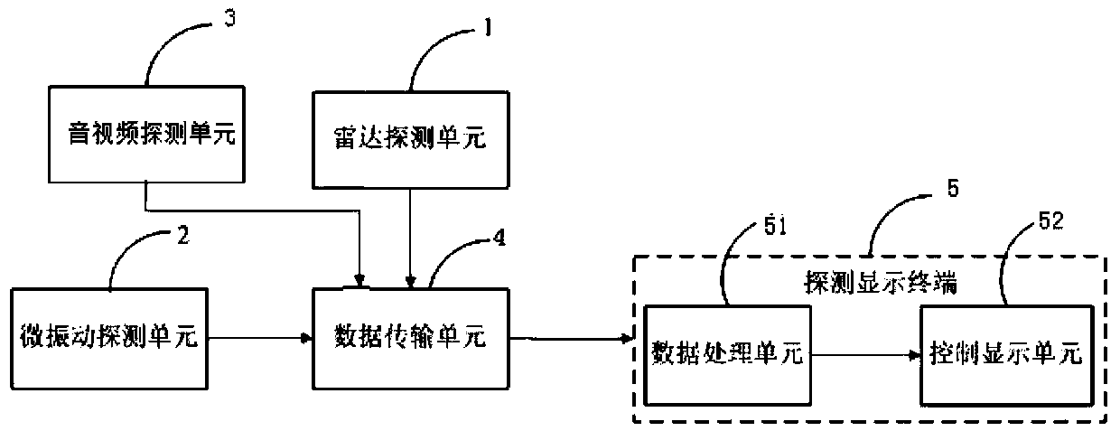
[0042] Such as figure 1 As shown, the multi-sensor fusion life detection and positioning system of the present invention includes:

[0043] The radar detection unit 1 is used to provide real-time detection data for the calculation of the three-dimensional positioning coordinates of living bodies under the ruins, and send the data to the data transmission unit 4 .

[0044] The micro-vibration detection unit 2 is used to detect the vibration signal and send it to the data transmission unit 4 .

[0045] The audio and video detection unit 3 is used to provide real-time detection data of images and sound waves for life under the ruins, so as to check the actual environment under the ruins, the location and signs of life, and provide more accurate rescue information through real-time dialogue. The detection data is sent to the data transm...


PUM


Abstract

The invention discloses a multi-sensor fusion life detection positioning system and positioning method. The system comprises a radar detection unit for providing real-time detection data for the computation of a three-dimensional positioning coordinate of a life entity under the ruins, and sending the real-time detection data to a data transmission unit; a micro-vibration detection unit for detecting a vibration signal; an audio-video detection unit for providing image and acoustic wave real-time detection data for the life entity under the ruins, checking the actual environment, the life entity location and physical sign information under the ruins, and providing more accurate rescue information through real-time conservation; the data transmission unit for receiving the detection data sent out by the radar detection unit, the micro-vibration detection unit and the audio-video detection unit and forwarding the same; and a detection display terminal for dynamically displaying the detection process and the detection result in real time. The method is implemented based on the above system. The system disclosed by the invention has the advantage of being simple in operation, wide in applicable range, and capable of greatly improving the life detection positioning precision.

Description

technical field [0001] The invention mainly relates to the technical field of life detection, in particular to a multi-sensing fusion life detection positioning system and a positioning method. Background technique [0002] The current domestic earthquake rescue life detection equipment is mainly two-dimensional radar life detector, audio and video detector and vibration audio life detector. Accurate rescue requirements. [0003] The radar life detection and positioning system based on the principle of the Doppler effect can penetrate several meters or even tens of meters of stone or concrete obstacles to detect and locate survivors under the ruins. However, in actual operation, this method of relying only on radar detection has the following problems: [0004] Radar life detection and positioning is to determine whether there is life and its orientation under the ruins after algorithmic analysis and processing of the reflected electromagnetic waves. However, due to the c...

Claims


Application Information

Patent Timeline
Patent Type & Authority Applications(China)
IPC IPC(8): G01V11/00
CPCG01V11/00
Inventor 熊毅王生水康琴屈胜
Owner HUNAN NOVASKY ELECTRONICS TECH
Why Eureka
Try Eureka