Pharmaceutical medicine particle screening equipment

A screening equipment and sieve plate technology, applied in the direction of filter screen, solid separation, grille, etc., can solve the problems of inconvenience for users, affect the screening efficiency, reduce the use efficiency, etc., and achieve the effect of novel design

Inactive Publication Date: 2019-12-10
JIANGSU FOOD & PHARMA SCI COLLEGE
View PDF9 Cites 13 Cited by
  • Summary
  • Abstract
  • Description
  • Claims
  • Application Information

AI Technical Summary

Problems solved by technology

[0003] In the process of pharmaceutical processing, it is necessary to screen the formed drug particles through screening equipment, but the screening effect of the existing screening equipment is poor, resulting in the need for manual screening by the user in the later stage, which increases the labor of workers Intensity reduces the use efficiency and is inconvenient for users to use, and the existing screening equipment is prone to the phenomenon of sieve hole jamming on the sieve plate during the screening process, resulting in poor screening effect and affecting screening efficiency

Method used


Image

  • Pharmaceutical medicine particle screening equipment
  • Pharmaceutical medicine particle screening equipment
  • Pharmaceutical medicine particle screening equipment

Examples


Embodiment 1

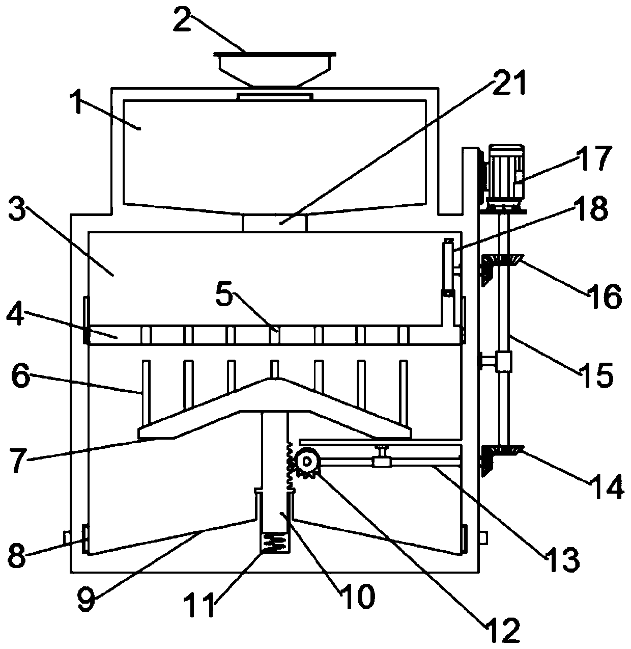
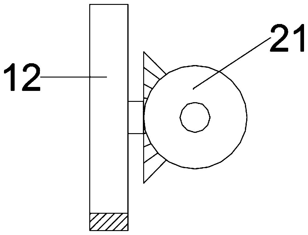
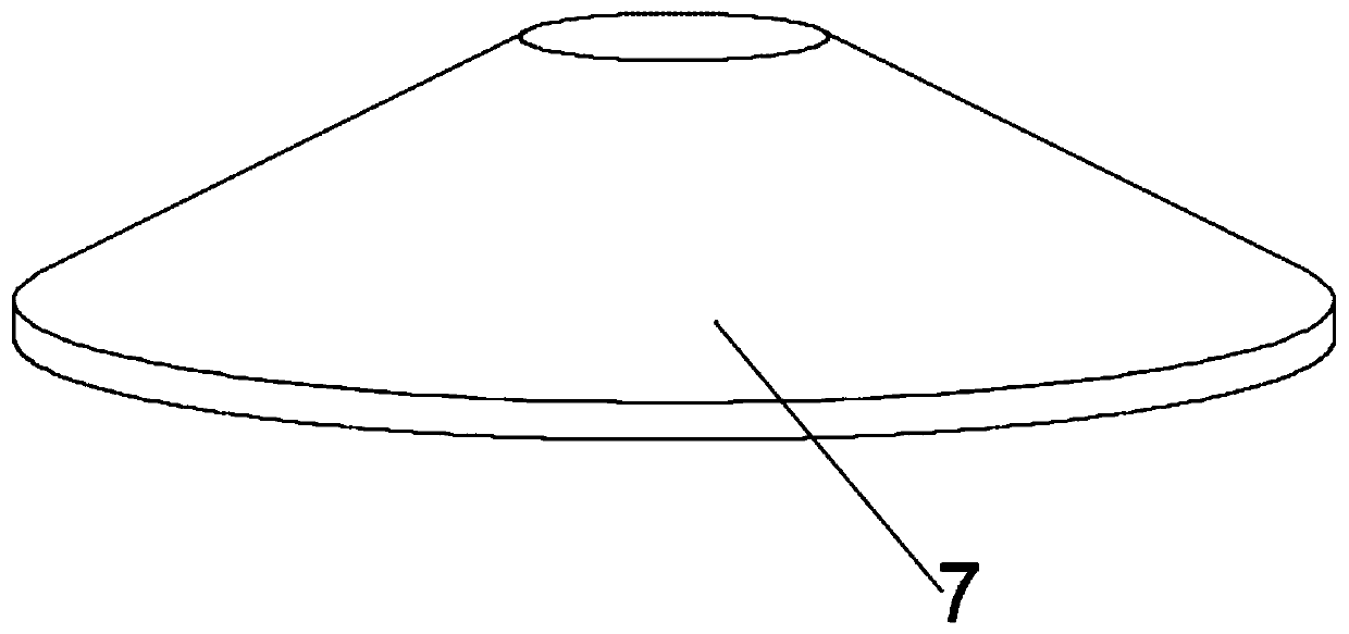
[0022] see Figure 1~3 , in an embodiment of the present invention, a kind of equipment for screening pharmaceutical drug particles, including a buffer chamber 1 and a screening chamber 3; the upper end of the buffer chamber 1 is provided with a feed hopper 2 communicating with it, and the screening chamber 3 is arranged in the buffer chamber 1 The lower end of the sieve plate 4 is connected to the lower end of the sieve cavity 3 through the drop hole 21. The sieve plate 4 is driven by the first drive assembly to move up and down reciprocally. The sieve plate 4 is provided with a plurality of holes for qualified medicine particles to fall A sieve hole 5, the bottom of the sieve plate 4 is provided with a guide plate 7 driven by the second drive assembly to move up and down, and the upper end of the guide plate 7 is provided with a plurality of tamping rods 6, and one of the tamping rods 6 is located in one Directly below the sieve hole 5, when the guide plate 7 moves upward, t...

Embodiment 2

[0030] see Figure 4 In the actual implementation process, the present invention provides another embodiment to improve the present application. Specifically, a baffle 19 is slidably installed at the junction of the buffer chamber 1 and the screening chamber 3, and one end of the baffle 19 is connected to the blanking The inner wall of the hole 21 contacts, and the other end is slidingly connected with the second eccentric wheel 20 fixed on the rotating shaft 16. When the rotating shaft 16 rotates, it drives the baffle plate 19 to move reciprocally, thereby realizing the reciprocating opening and closing of the blanking hole 21, realizing The medicine particles in the buffer chamber 1 are fed intermittently, so as to prevent a large amount of medicine particles from being above the sieve plate 4 and affect the screening efficiency.


PUM


Abstract

The invention relates to the technical field of screening, in particular to pharmaceutical medicine particle screening equipment. The pharmaceutical medicine particle screening equipment comprises a buffering cavity and a screening cavity. wherein a feeding hopper communicating with the buffering cavity is arranged at the upper end of the buffering cavity, the screening cavity is arranged at the lower end of the buffering cavity, and communicates through a discharging hole, and a sieve plate driven by a first driving assembly to move up and down is arranged on the inner side of the screening cavity, a sieve plate is provided with a plurality of sieve holes used for falling of qualified medicine particles, a guide plate driven by a second driving assembly to move up and down is arranged below the sieve plate, a plurality of pounding rods are arranged at the upper end of the guide plate, one pounding rod is located right under one sieve hole, and when the guide plate moves upwards, the pounding rods upwards move into the sieve holes. According to the pharmaceutical medicine particle screening equipment, the design is novel, an effective flow guide effect is achieved through the arranged guide plate, and meanwhile, the plurality of pounding rods arranged on the guide plate are intermittently inserted into the sieve holes in the sieve plate, so that the sieve holes are prevented from being blocked to influence the screening effect.

Description

technical field [0001] The invention relates to the technical field related to screening, in particular to a screening device for pharmaceutical drug granules. Background technique [0002] Drugs are substances used to prevent, treat and diagnose disease. In theory, drugs refer to any chemical substances that can affect the physiological functions of the body's organs and cell metabolism activities, which belong to the category of drugs. [0003] In the process of pharmaceutical processing, it is necessary to screen the formed drug particles through screening equipment, but the screening effect of the existing screening equipment is poor, resulting in the need for manual screening by the user in the later stage, which increases the labor of workers Intensity reduces the use efficiency and is inconvenient for users to use, and the existing screening equipment is prone to the phenomenon of sieve hole jamming on the sieve plate during the screening process, resulting in poor s...

Claims


Application Information

Patent Timeline
Patent Type & Authority Applications(China)
IPC IPC(8): B07B1/34B07B1/46B07B1/42B07B1/50
CPCB07B1/343B07B1/42B07B1/46B07B1/50
Inventor 黄秀锦谭佩毅
Owner JIANGSU FOOD & PHARMA SCI COLLEGE
Why Eureka
Try Eureka