Clamp and method for polishing plane optical part

A technology of optical parts and fixtures, applied in optical surface grinders, grinding/polishing equipment, manufacturing tools, etc., can solve the problems of prolonging processing time, chipping, and long time, and achieve improved product qualification rate, convenient disassembly, and easy operation simple effect

Pending Publication Date: 2019-12-10
安徽光智科技有限公司
View PDF0 Cites 5 Cited by
  • Summary
  • Abstract
  • Description
  • Claims
  • Application Information

AI Technical Summary

Problems solved by technology

However, the dispensing and loading method has the following adverse effects in the two steps of loading and unloading: 1. Before loading, the protected surface of the part needs to be protected. Generally, two layers of protective paint or pasting PET are used. The method of protective film, after that, evenly draw lines with asphalt-dissolved gasoline on the protected surface, select the appropriate number of lines according to the size of the blank, and wait for 2 hours to dry the gasoline before dispensing and putting on the plate
And a part generally needs to be dispensed with 16-20 points of glue, which takes about 15 minutes, so the preparation work before loading and the loading process take a long time, resulting in a long time-consuming overall processing; 2. Processing parts after loading , there will be the following processing risks: (1) Disc loss, because the parts and the surface of the polishing mold do not run together, a large tensile force is generated, and the dispensing cannot bear it and breaks, so that the parts are separated from the rubber mold, and the disc is lost. Optical parts It is easy to collide with the plastic mold or machine in the process of dropping the disk, and the edges may be chipped or even damaged; (2) Multiple dispensing glues are required to bond the optical parts when loading the disk, and the dispensing will generate a certain tension on the parts, resulting in processing on the disk Sometimes the parts are not easy to meet the aperture requirements, and the processing time needs to be extended; 3. After the parts are removed from the plate, they will also be subject to the tension of dispensing, which will cause the aperture of the optical parts to increase or deform, resulting in unqualified products

Method used


Image

  • Clamp and method for polishing plane optical part
  • Clamp and method for polishing plane optical part
  • Clamp and method for polishing plane optical part

Examples


Embodiment 1

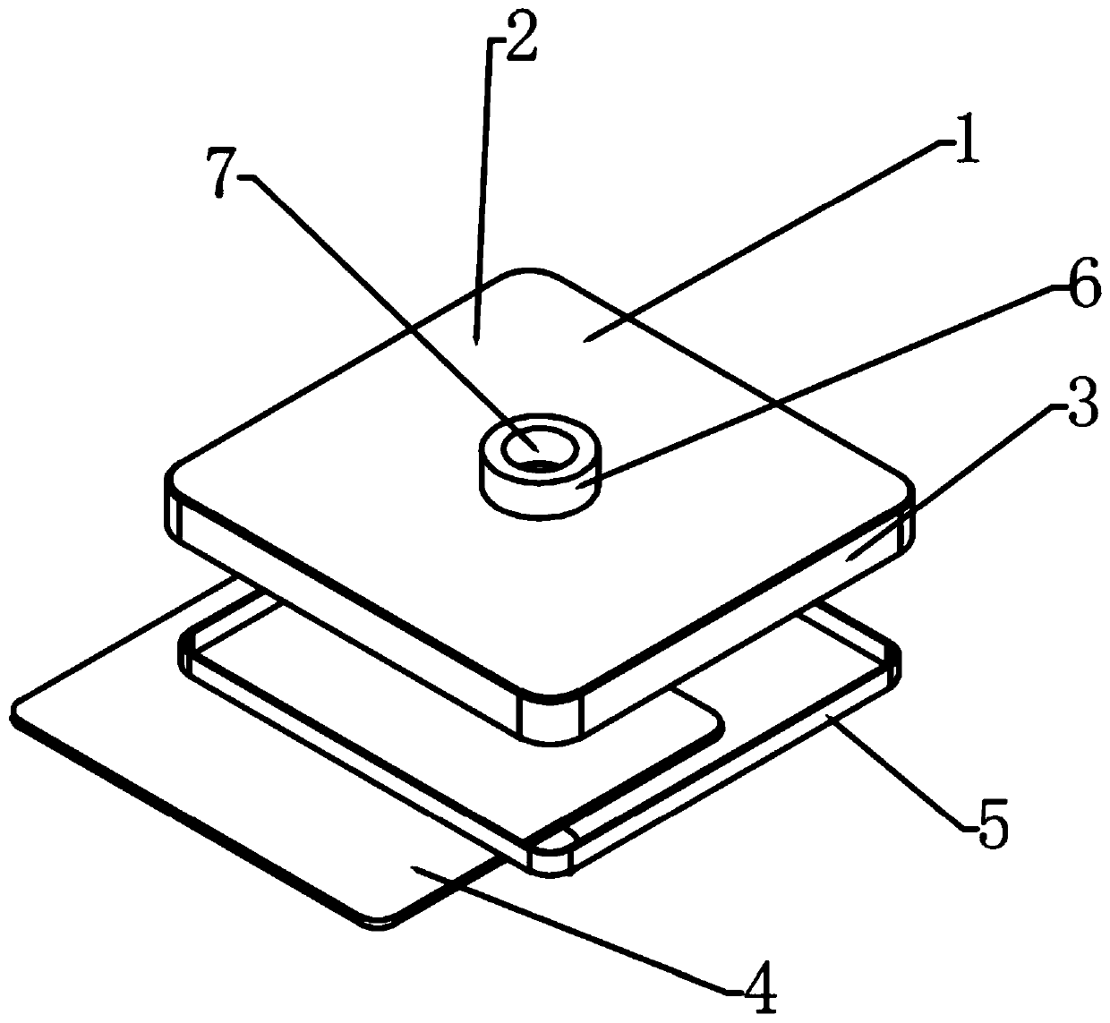
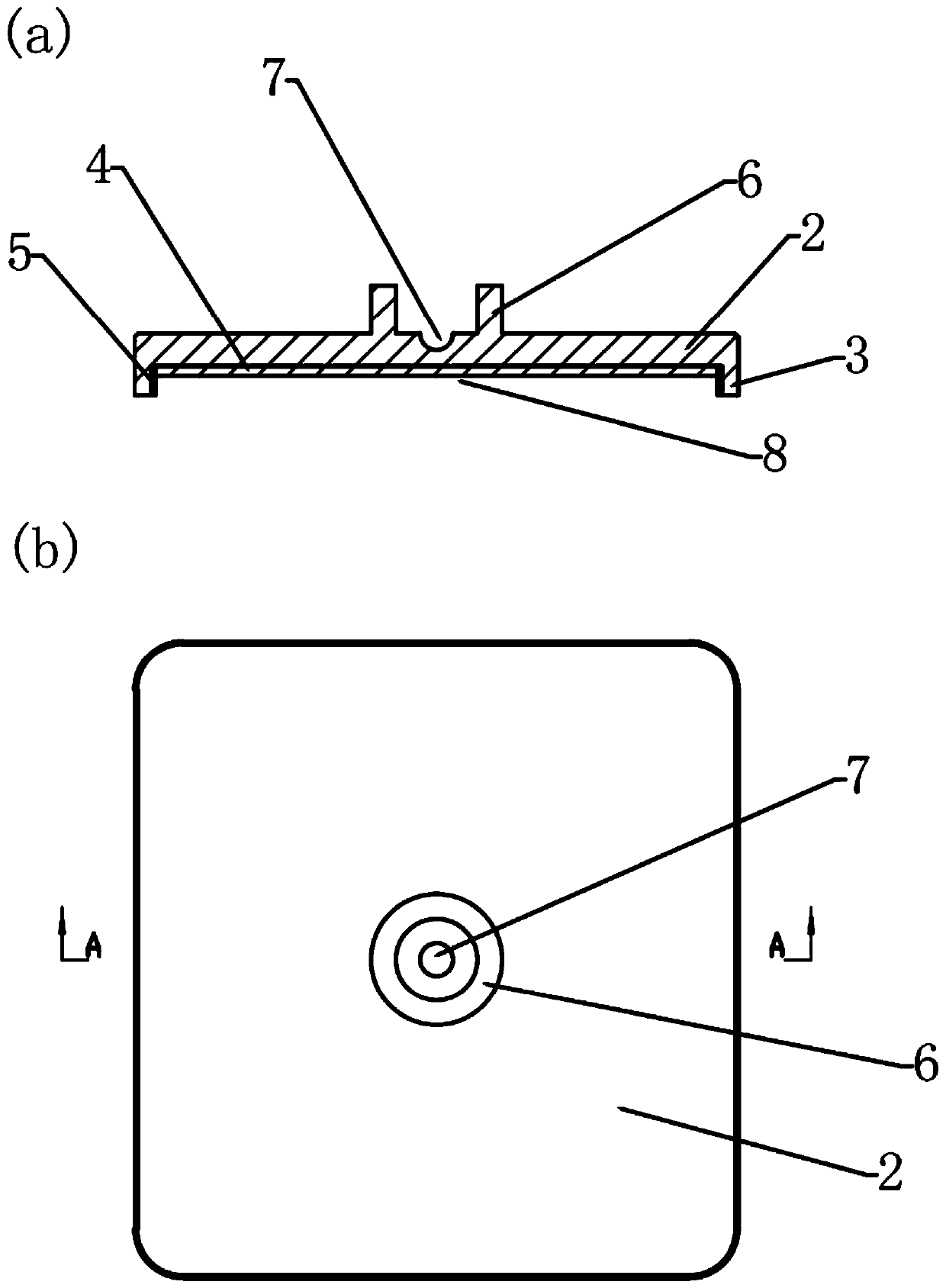
[0040] A kind of fixture that is used for the polishing of planar optical part as the embodiment of the present invention, as figure 1 , figure 2As shown, the clamp 1 is a clamp with a rectangular groove shape, the clamp includes a base 2 and a rib 3, the base 2 is a rectangular plate, and a rib 3 is fixed around the base, and the rib 3 and the The base 2 is vertical, the rib 3 and the base 2 form a groove 8, the depth of the groove 8 is smaller than the thickness of the planar optical part, and the opposite side of the groove surface of the base is provided with a grinding and polishing machine The screw thread 6 that the main shaft cooperates and the stylus hole 7 that cooperates with the stylus of grinding and polishing machine; The bottom surface protection pad 4 is arranged in the groove of described clamp, and the shape of the bottom surface protection pad 4 is consistent with the shape of the bottom surface of the groove, The material of the bottom protection pad is d...

Embodiment 2

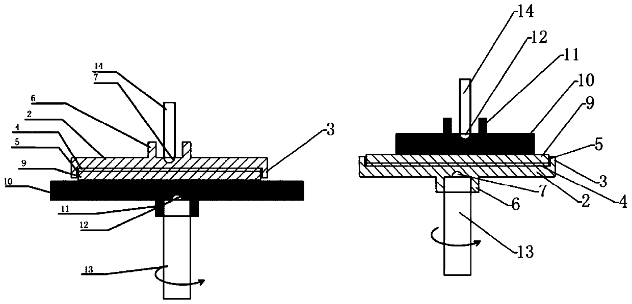
[0053] A kind of fixture that is used for the polishing of planar optical part as the embodiment of the present invention, as image 3 As shown, the only difference between this embodiment and Embodiment 1 is: the bottom surface of the groove is provided with several vertical and horizontal slots, the slots are parallel to the ribs, and the two ends of the slots extend to the Said edge, the clamp also includes an insert that fits with the slit, the insert is a sheet, and the height of the insert when it is inserted on the slit is the same as the height of the edge Consistent, the bottom surface of the groove is provided with 6 longitudinal slits 15, the bottom surface of the groove is provided with 6 transverse slits 16, the two ends of the longitudinal slits extend to the rib, and the transverse slits The two ends of each extend to the rib, the longitudinal slits are perpendicular to the transverse slits, the longitudinal slits are arranged at intervals from the ribs, and the...


PUM

PropertyMeasurementUnit
thicknessaaaaaaaaaa
particle sizeaaaaaaaaaa

Abstract

The invention provides a clamp and method for polishing a plane optical part. The clamp is a clamp with a rectangular groove shape, and the clamp comprises a base and blocking edges, wherein the baseis a rectangular plate, the periphery of the base is fixedly provided with the blocking edges, and the blocking edges are perpendicular to the base; a groove is defined by the blocking edges and the base, wherein the depth of the groove is smaller than that of the plane optical part; and threads matched with a main shaft of a grinding and polishing machine or a stylus hole matched with a stylus ofthe grinding and polishing machine is arranged on the other surface opposite to the groove surface of the base. According to the clamp and method for polishing the plane optical part, the plane optical part can be directly placed into the clamp when the clamp is used for polishing the plane optical part so that grinding, polishing and other processes can be carried out, and the plane optical partis conveniently taken out after being machined; and meanwhile, the base of the clamp base is provided with the stylus hole or the threads, so that disassembling is convenient, the operation is simple, the damage caused by falling of the optical part is avoided, and the potential deformation caused by taking-out of the plane optical part after machining is finished through a dispensing method is also avoided, so that the product qualifying rate is improved.

Description

technical field [0001] The invention relates to the field of optical parts polishing equipment, in particular to a fixture and method for polishing planar optical parts. Background technique [0002] The classical polishing method is the main method used in the processing of high-precision optical parts in my country, mainly including the processes of upper plate, grinding, rough polishing, fine polishing, and lower plate. Mounting and lowering are important processes in the classical polishing method. Mounting refers to the bonding of optical parts to the plastic mold. The common mounting methods are spot glue, light glue, and embossed glue, etc. The most commonly used method is the dispensing and loading method. Because the shape of some optical parts is relatively symmetrical, there is no need to add auxiliary parts for processing when these parts are placed on the plate, and they can be directly placed on the plate. Protect the non-processed surface of the optical parts...

Claims


Application Information

Patent Timeline
Patent Type & Authority Applications(China)
IPC IPC(8): B24B1/00B24B13/00B24B13/005
CPCB24B1/00B24B13/0018B24B13/005
Inventor 尹士平黄跃华王艺娜陆媛新春
Owner 安徽光智科技有限公司
Why Eureka
Try Eureka