A batching device for particle spraying equipment
An equipment and particle technology, applied in abrasive feeding devices, metal processing equipment, abrasives, etc., can solve the problems of complex compressed gas operation routes, uneven distribution of dry ice transport pits, uneven ingredients, etc., to reduce manual maintenance, The effect of reducing residual amount and ensuring continuity
- Summary
- Abstract
- Description
- Claims
- Application Information
AI Technical Summary
Problems solved by technology
Method used
Image

Examples
Embodiment 1
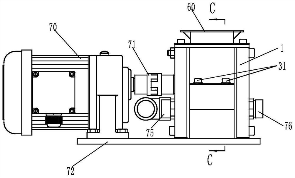
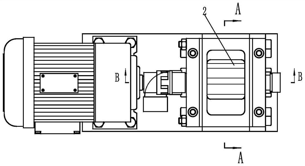
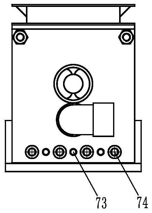
[0034] Such as figure 1 , figure 2 and image 3 Shown is the dosing device of the particle spraying equipment disclosed in the present invention, including a box body 1 and a dosing shaft 2, in this embodiment, as Figure 4 , Figure 5 and Figure 7 As shown, the box body includes a base 11, two support plates 12, an upper sealing block 13 and a lower sealing block 14, and the two support plates 12 are respectively fixed to the two ends of the base 11, specifically, the support plate 12 are respectively limited on the base by pins 73 and fixed by fastening bolts 74, the lower sealing block 14 is placed between the two support plates 12 and installed on the base 11, the upper sealing block The block 13 is placed on the upper part of the lower sealing block 14 and is fixedly connected with the two support plates 12, such as Figure 8 and Figure 9As shown, the upper sealing block 13 has an upper batching shaft installation cavity 131, and the lower sealing block 14 has a ...
Embodiment 2
[0042] Such as Figure 13 and Figure 14 Shown is the second embodiment of the batching device of the particle spraying equipment disclosed in the present invention. The difference between this embodiment and Embodiment 1 is that, in Embodiment 1, the batching groove 20 on the batching shaft 2 and the batching shaft The axes are parallel, and in Embodiment 2, the batching groove 20 forms a certain angle with the axis of the batching rotating shaft 2 .
[0043] Such as Figure 15 Shown is the motion analysis diagram (plan view) when the material reaches the air inlet with the rotation of the batching shaft in the batching groove in embodiment 1. The material rotates together with the batching shaft in the batching groove. When the material just When reaching the air inlet, the material has a horizontal velocity V1, and the batching shaft has a horizontal speed V3, V1=V3. With the rotation of the batching shaft, the batching groove moves in a circular motion, and the material ...
PUM
 Abstract
Description
Claims
Application Information