Sewage treatment flocculant rapid mixing equipment
A technology of mixing equipment and sewage treatment, applied in water/sewage treatment, water/sludge/sewage treatment, flocculation/sedimentation water/sewage treatment, etc. problems, to achieve the effect of reducing labor intensity, speeding up processing speed, and preventing excessive sewage
- Summary
- Abstract
- Description
- Claims
- Application Information
AI Technical Summary
Problems solved by technology
Method used
Image

Examples
Embodiment 1
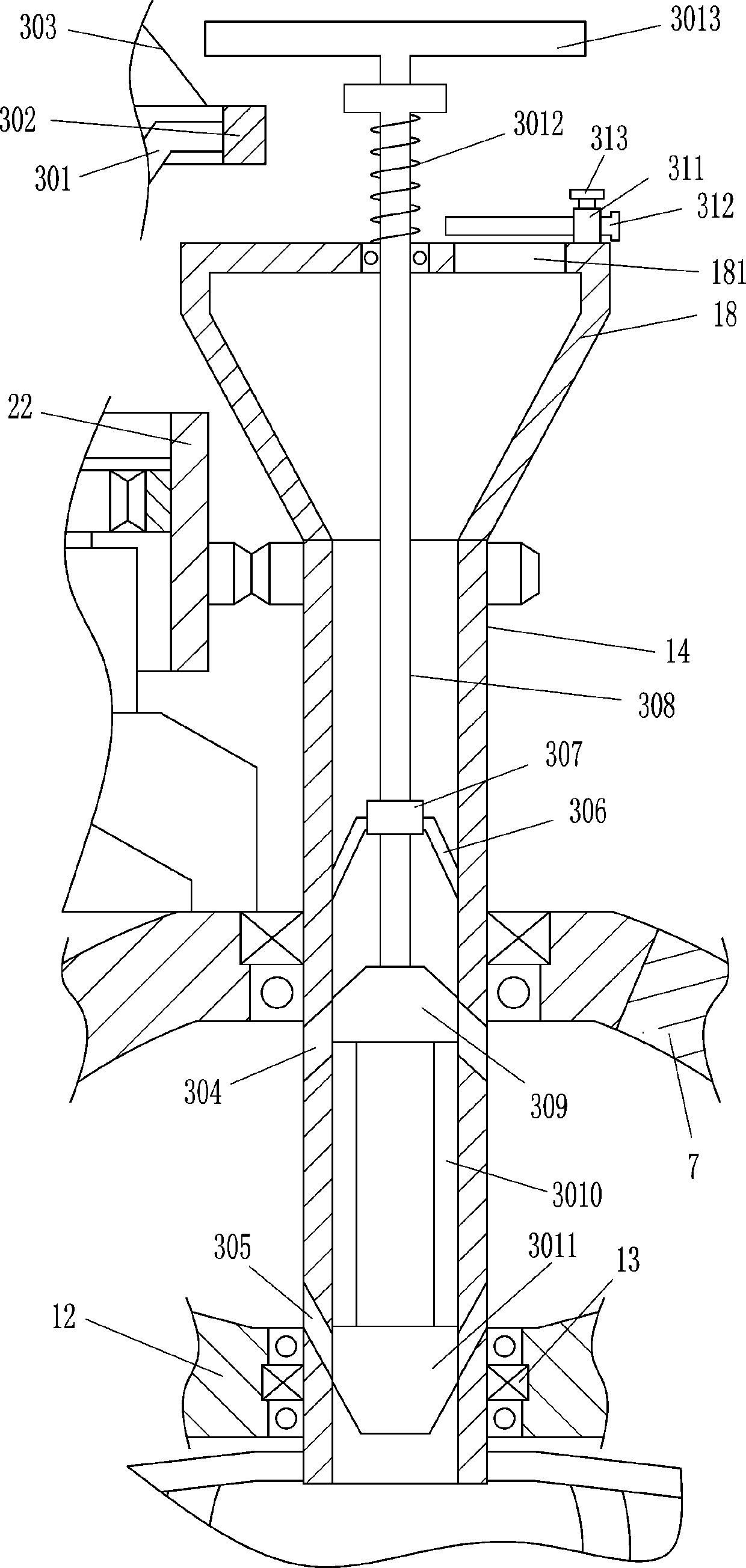
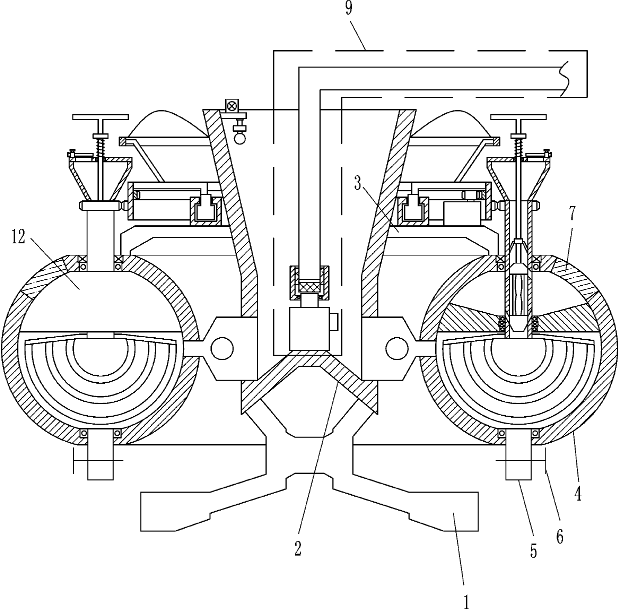
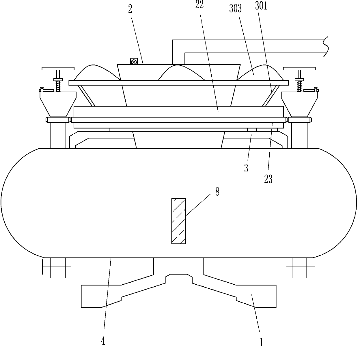
[0019] A sewage treatment flocculant rapid mixing equipment, such as Figure 1-5 As shown, it includes an underframe 1, a water storage tank 2, a support frame 3, an annular box 4, a downpipe 5, a first valve 6, a first observation window 7, a second observation window 8, a water suction device 9, and a water outlet joint 10 , the second valve 11, the blocking box 12, the first bearing seat 13, the drum 14, the connecting rod 15, the stirring rod 16, the first gear 17, the flocculant placing bucket 18, the ring slide rail 19, the slider 20, the L-shaped Rod 21, rotating ring 22, second gear 23, ring gear 24, drive motor 25 and third gear 26, water storage tank 2 is installed on the top of underframe 1, underframe 1 is connected with water storage tank 2 by welding connection, the left and right sides of the upper part of the water storage tank 2 are fixedly connected with a support frame 3, and an annular box 4 is installed between the outer sides of the left and right two sup...
Embodiment 2
[0021] A sewage treatment flocculant rapid mixing equipment, such as Figure 1-5As shown, it includes an underframe 1, a water storage tank 2, a support frame 3, an annular box 4, a downpipe 5, a first valve 6, a first observation window 7, a second observation window 8, a water suction device 9, and a water outlet joint 10 , the second valve 11, the blocking box 12, the first bearing seat 13, the drum 14, the connecting rod 15, the stirring rod 16, the first gear 17, the flocculant placing bucket 18, the ring slide rail 19, the slider 20, the L-shaped Rod 21, rotating ring 22, second gear 23, ring gear 24, drive motor 25 and the 3rd gear 26, the top of underframe 1 is equipped with water storage tank 2, and the left and right sides of water storage tank 2 tops are all fixedly connected with Support frame 3, annular box 4 is installed between the outer sides of the bottoms of the left and right two support frames 3, and the left and right sides of the bottom of the annular box...
Embodiment 3
[0024] A sewage treatment flocculant rapid mixing equipment, such as Figure 1-5 As shown, it includes an underframe 1, a water storage tank 2, a support frame 3, an annular box 4, a downpipe 5, a first valve 6, a first observation window 7, a second observation window 8, a water suction device 9, and a water outlet joint 10 , the second valve 11, the blocking box 12, the first bearing seat 13, the drum 14, the connecting rod 15, the stirring rod 16, the first gear 17, the flocculant placing bucket 18, the ring slide rail 19, the slider 20, the L-shaped Rod 21, rotating ring 22, second gear 23, ring gear 24, drive motor 25 and the 3rd gear 26, the top of underframe 1 is equipped with water storage tank 2, and the left and right sides of water storage tank 2 tops are all fixedly connected with Support frame 3, annular box 4 is installed between the outer sides of the bottoms of the left and right two support frames 3, and the left and right sides of the bottom of the annular bo...
PUM
 Abstract
Description
Claims
Application Information
 - R&D
- Intellectual Property
- Life Sciences
- Materials
- Tech Scout
- Unparalleled Data Quality
- Higher Quality Content
- 60% Fewer Hallucinations
Browse by: Latest US Patents, China's latest patents, Technical Efficacy Thesaurus, Application Domain, Technology Topic, Popular Technical Reports.
© 2025 PatSnap. All rights reserved.Legal|Privacy policy|Modern Slavery Act Transparency Statement|Sitemap|About US| Contact US: help@patsnap.com