Humidity regulating part and dehumidifier

A technology of humidity adjustment and dehumidifier, which is applied in the direction of air conditioning system, heating method, lighting and heating equipment, etc., to achieve the effect of accelerating air flow, small size and strong dehumidification ability

Pending Publication Date: 2019-12-10
宋伟增
View PDF25 Cites 2 Cited by
  • Summary
  • Abstract
  • Description
  • Claims
  • Application Information

AI Technical Summary

Problems solved by technology

[0003] The object of the present invention is to provide a humidity regulator and a dehumidifier. The technical problem to be solved is to improve the existing dehumidifier, so that the dehumidifier not only has a compact structure, a small volume, and is easy to operate, but also has a large dehumidification capacity and a strong dehumidification capacity.

Method used


Image

  • Humidity regulating part and dehumidifier
  • Humidity regulating part and dehumidifier
  • Humidity regulating part and dehumidifier

Examples


Embodiment Construction

[0063] In order to further explain the technical means and effects of the present invention to achieve the intended purpose of the invention, the specific implementation, features and effects of the humidity regulator and dehumidifier according to the present invention will be described below in conjunction with the accompanying drawings and preferred embodiments. , as detailed below.

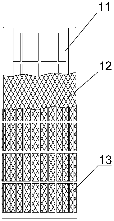
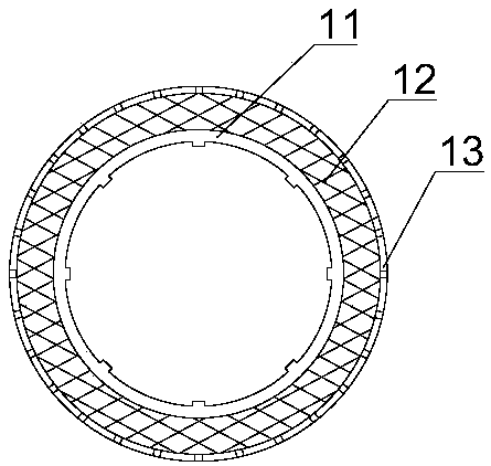
[0064] The present invention relates to a humidity regulating member, which is a cylinder 10 with a through hole. Specifically, see figure 1 , figure 2 , the cylinder body 10 includes a cylindrical keel 11 and a functional layer 12, the cylindrical keel 11 is used for support, the functional layer 12 is used for attaching dehumidification liquid, the functional layer 12 is coated on the cylindrical keel 11, and the functional layer 12 and the cylindrical keel 11 is fixed to each other. Specifically, the functional layer 12 includes a multi-layer cylindrical screen, the keel and the functiona...


PUM


Abstract

The invention relates to a dehumidifier. The dehumidifier comprises a housing, dehumidifying liquid, a humidity regulating piece and a dehumidifying fan, wherein an air inlet and an air outlet are formed in the housing; the dehumidifying liquid is placed in the housing and used for adsorbing moisture in air; the humidity regulating part is connected with a driving device; the driving device drivesthe humidity regulating piece to rotate; a part of the humidity regulating part is immersed in the dehumidifying liquid; the dehumidifying liquid is attached to the humidity regulating part in the rotating process; and the dehumidifying fan is arranged in the housing. The dehumidifier is compact in structure, small in size, simple and convenient to operate, high in dehumidification number and high dehumidification capacity.

Description

technical field [0001] The invention relates to an air conditioning device, in particular to a dehumidifier. Background technique [0002] Commonly used dehumidifiers include refrigerated dehumidifiers and liquid dehumidifiers. The refrigerated dehumidifier has a compact structure, small volume, and simple operation, but the dehumidification capacity is small and the dehumidification effect is poor; while the liquid dehumidifier has a large dehumidification capacity and strong dehumidification ability, but due to its The dehumidification device and the reduction device adopt the spraying method, which makes the structure of the dehumidifier complex, bulky, inconvenient to operate, and high in cost. Contents of the invention [0003] The purpose of the present invention is to provide a humidity regulator and a dehumidifier. The solution is to improve the technical problems of the existing dehumidifiers, so that the dehumidifier not only has a compact structure, small volume...

Claims


Application Information

Patent Timeline
Patent Type & Authority Applications(China)
IPC IPC(8): F24F5/00F24F3/14B01D53/26
CPCF24F5/00F24F3/1417B01D53/261F24F2003/144
Inventor 宋伟增
Owner 宋伟增
Why Eureka
Try Eureka